Phase 8 Details
MRP Redditt 15 Mar 14 – 23 Mar 14
Introduction and Personal Observations:
Hello there! Well, another MRP has been concluded, and I must say that – while we wanted to get more done out there – at least we were able to get a fair bit of the taskings completed. (Or, at least to a point where the initial work is done and we have a better understanding of what’s required to bring that Sub System up to “Serviceable” Status.)
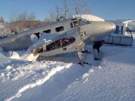
Enjoyable as these MRP’s are – there is the end point that we really need to get to, but the big question (that I’m sure people are asking) is why it’s taking us so long to get the aircraft “Serviceable”? Well, first and foremost, she hasn’t flown since January of 1975. (That – right there – is the main concern that I have.) Lot’s of time expired items, lots of items that need to be replaced, lots of extra work and the high potential for hidden problems right there – and on top of that there are the electrical issues that the aircraft has. (The wiring is original to 1951, and there have been a lot of substandard work done since then. As a matter of fact, since MRP 2013 was completed, I’m becoming more and more convinced that the aircraft was grounded for electrical reasons.) But, more on the electrical issues later.
Lots of money is needed to returning – and keep flying! – a vintage aircraft, which gives a great deal of weight to the expression “Never feel sorry for a guy who owns an airplane”. (And, it doesn’t help matters that I currently own two airplanes.) So, one of the delays is the fact that it takes time to earn the money necessary to do the MRP at all – never mind have the parts inspected and overhauled. (Seeing that my maintenance crew is all volunteer, the deal is that I pick up the tab for the transportation and the accommodations for those who come out on the MRP.) And, it’s important to note that the deal doesn’t cover the expenses for the rations for the individual crew member.
Let’s be honest, though - all that time between the MRP’s isn’t wasted, either.
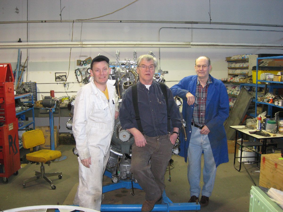
Outside of the MRP, I’m volunteering at the Alberta Aviation Museum as much as possible – specifically in the Engine Bay (where we are currently working on a B-25 Engine) and in the Technical Library. Not only is it a good deal of fun, but it’s also a valuable learning experience because I’m getting the chance to learn directly from the veterans. For example, my boss (in the Engine bay) is Cpl (ret) Roy Elder, RCAF – and he used to work on Neptunes and Lancasters.
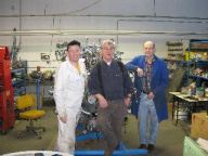
Balodis, Ed, and Roy Elder
MRP Participation also requires that all of us participate in Publication Exercises, or PubEx’s. What we do with that tasking is we sit down with the Aircraft Operating Instructions, the Maintenance Manual, the Parts Manual, and any other reference material that all of us have access to. At that point, one of us will take the turn for the week and sit down to write up the PubEx – asking very specific questions (requiring very specific references, in addition to the answers) about a particular system that may catch their eye, or a part that will be removed during the upcoming MRP.
Your answer is very important – but the main take away here is that all of us are getting more familiar with the maintenance manuals. (And, the key take away is that all of us are getting familiar with the manuals long before we get out there.) Because once we’re out there, there really isn’t the time to figure out that we really don’t know all that we should about a particular part or system. Here’s an example of one of the PubEx’s that we did.
Databases to finish, tools to purchase and the non-stop searching for parts and manuals also take up an ever increasing amount of my time. At times, I ask myself, “Is it possible that I may be doing too much by being a perfectionist when it comes to maintenance in general and this restoration specifically?”
Easy answer: “Perhaps.” But then, I’m the Crew Chief.
As a matter of fact, that’s my job.
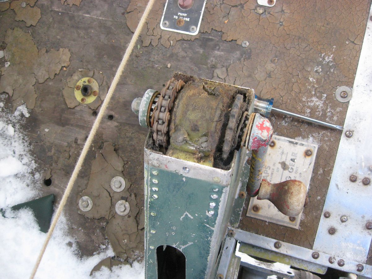
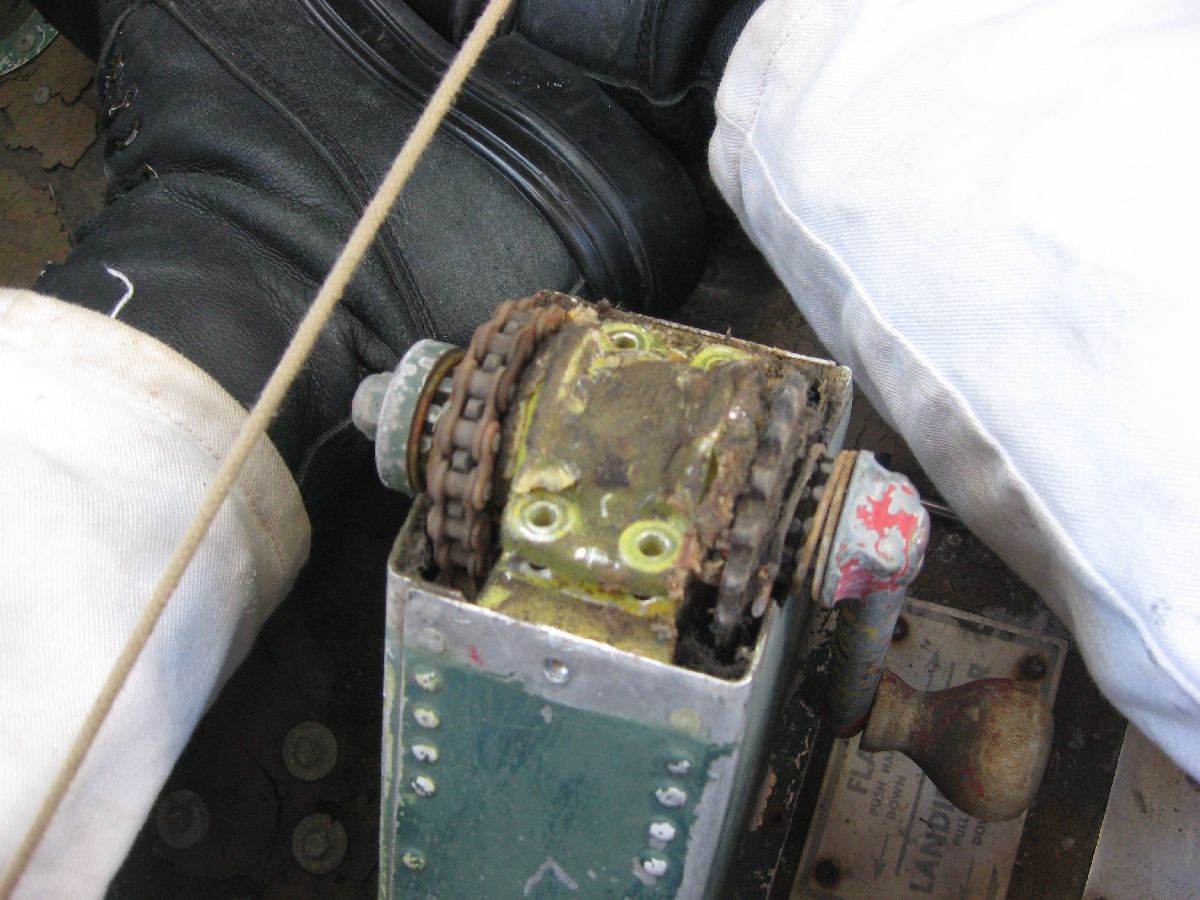
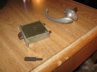
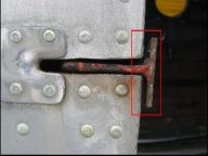
Remove Landing Gear and Emergency Flap Handcrank
Removing the hand crank was a big focus for working in the cockpit – and not just because it’s an old part that hasn’t been inspected, serviced or maintained since the aircraft last flew. There were other considerations in addition to that one – space. (Specifically, the amount of space that’s available in the cockpit to move around when work is needed to be done.)
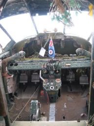
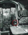
MRP 2013 Photo of Cockpit
Having already spent some time in a Beech 18 Cockpit – or worse – under the Sub Panel Assemblies or working behind the Centre Control Console – you really appreciate just how much room you just don’t have to move around. (Matter of fact, most times you’ve got just enough room to get into a particular spot only one way. And, right after you’ve almost literally folded yourself into a small area – that’s when you remember that you’ve forgotten either your flashlight or a vital tool!) So, the removal of the Landing Gear and Emergency Flap Handcrank – while a mechanical necessity – was also important to do in relation to the larger amounts of maintenance (and removal) of parts that were planned for the cockpit on this MRP.
Optimistically, I wish I could say that it was a flawless removal with no problems. (I also wish that I could say that it took next to no time to remove it, too.) However, that really wouldn’t be the truth. Due to almost 40 years of corrosion (and the added bonus of snow and cold) it was removed – only it took a little longer than anticipated or planned for.
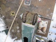

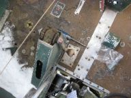

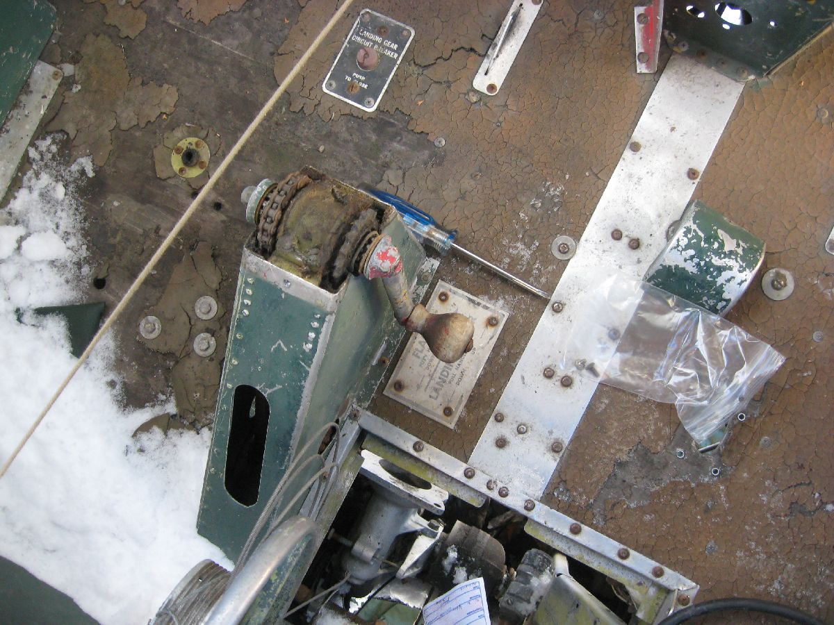
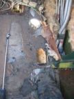
Removing the Handcrank Photos
Taking our time (even with the weather challenges), it was removed – safely, carefully, and properly.
Moving on to the next tasking!
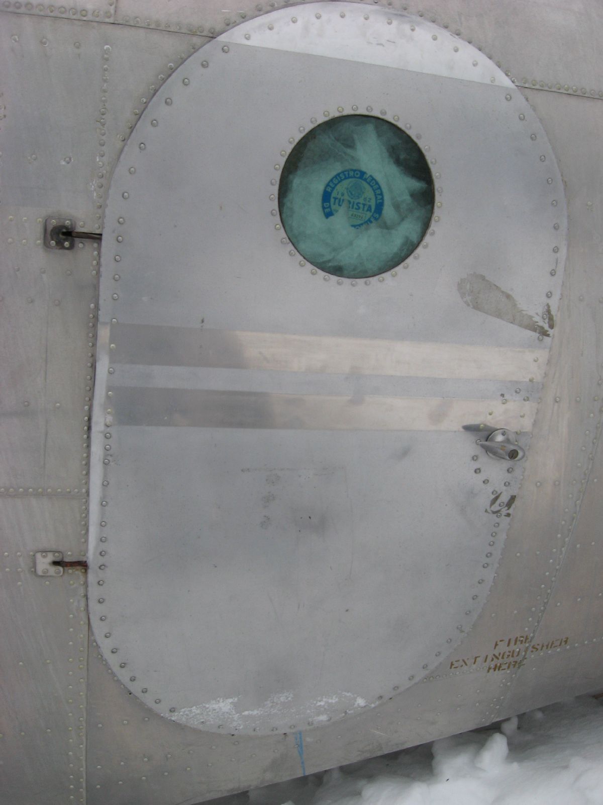
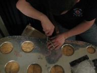
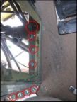
Nose Door Assembly
As optimistic as it sounds, it really was hoped that the Nose Door Assembly would get changed out – in addition to the new hardware and other assigned tasked completed.
Clearly, we ran into problems with this PO.
Guess who?
Photo Credit: J. Hudson
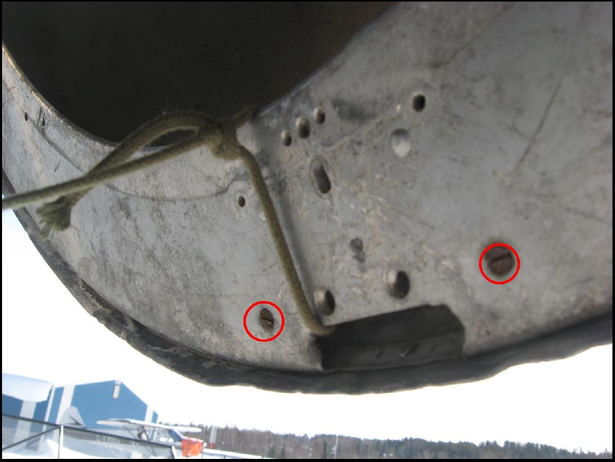
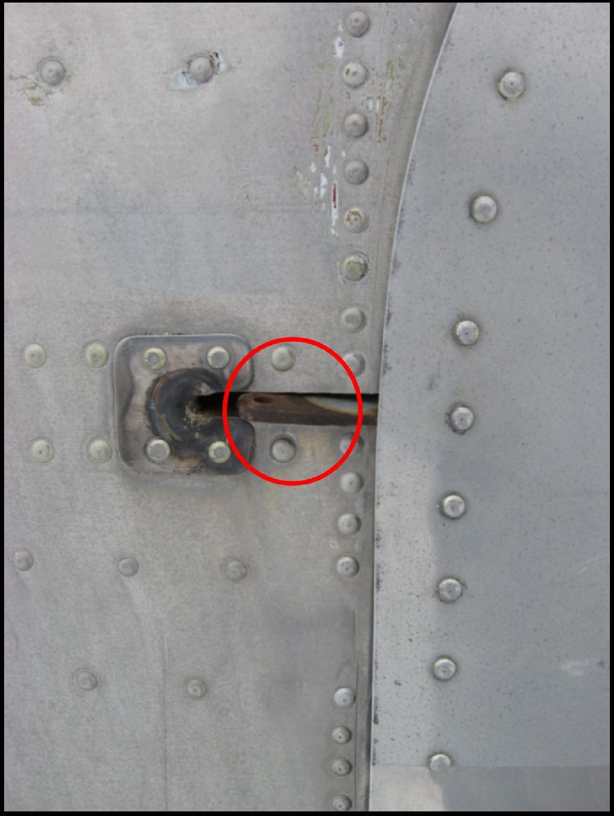
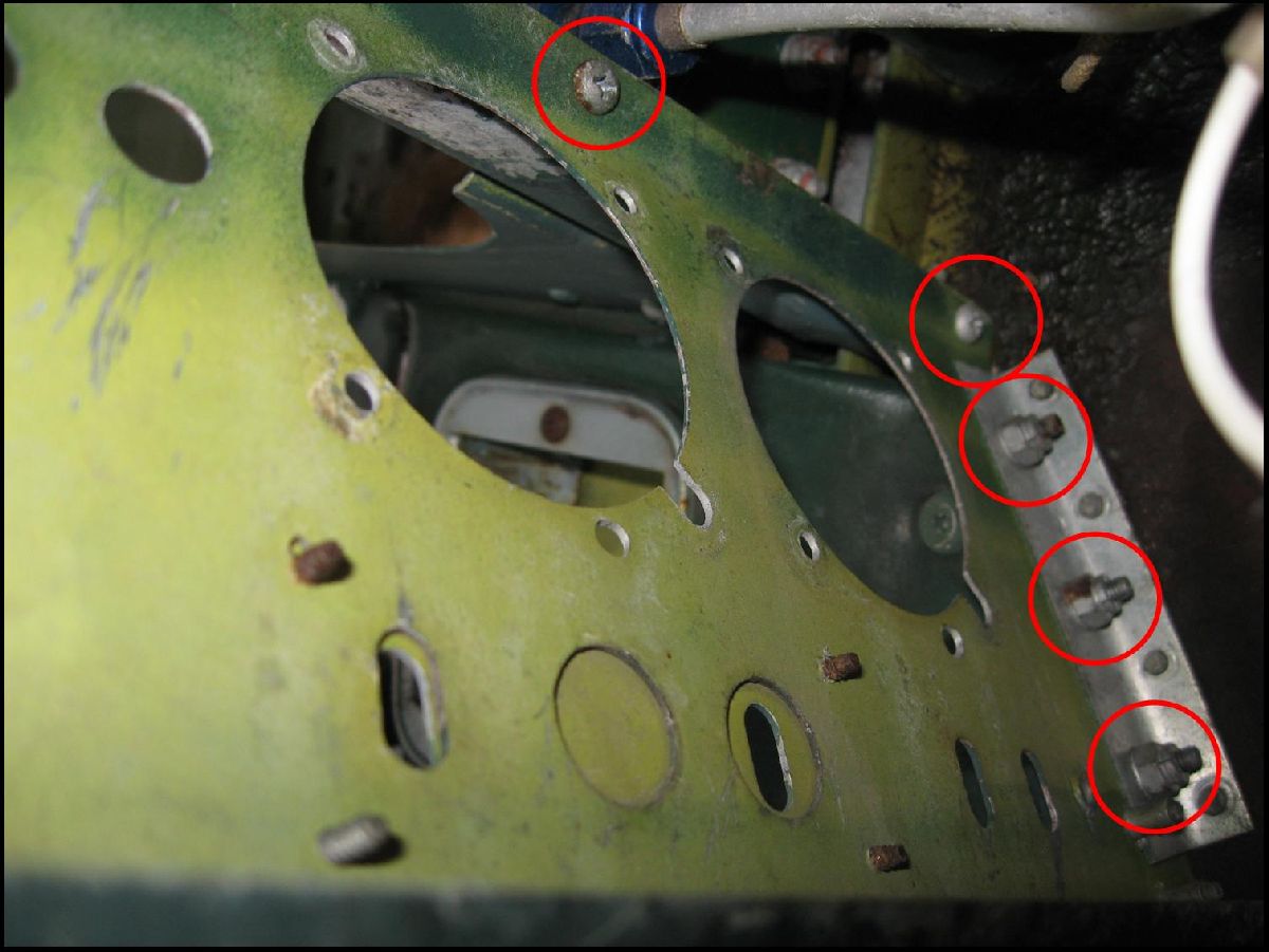
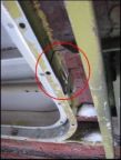
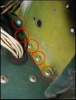
In addition to the snow (and cold) we were dealing with corroded hardware again – this time, the hardware in the Nose Door itself.
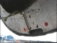
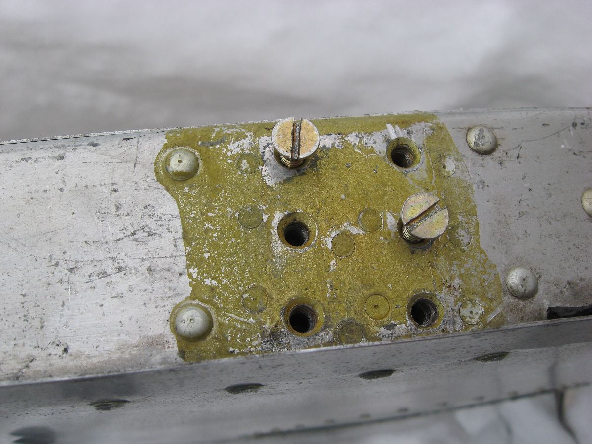
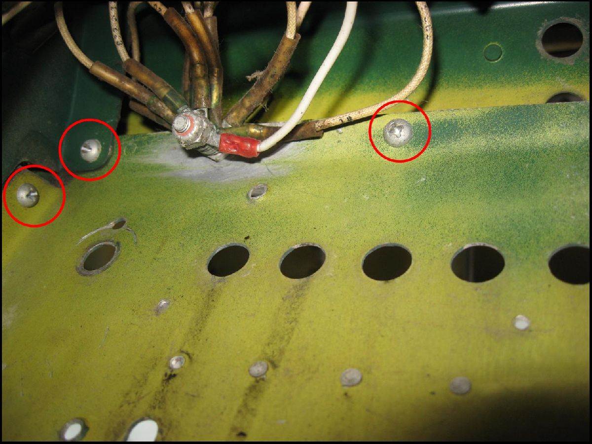
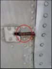
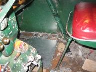
Corroded Screws circled
Luck is what we needed with the hardware – at least when it came down to trying very hard to remove it in less than ideal conditions. However, this corrosion made it so that it just wasn’t possible to remove the old hardware. (The real problem is that the hardware simply wasn’t designed to sit for almost 40 years in all kinds of weather.) At that point, it takes a great deal of skill and luck to remove old hardware that is well past their point of being removed.
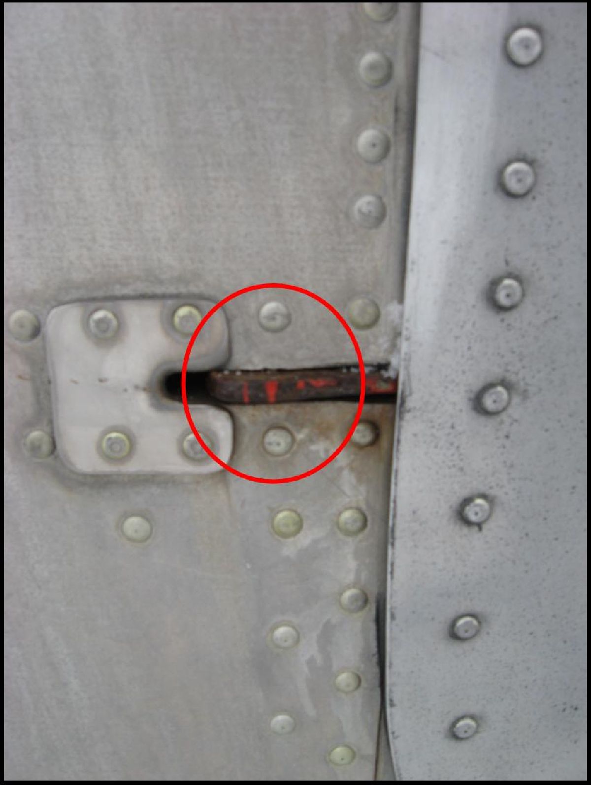
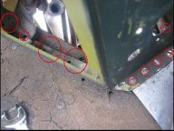
Catching a break with the hardware removal would have meant that we could have been able to change out the parts – and thus, gave a good chance of completing the tasking. However, that wasn’t the case here, so – in turn – the problem had a snowball effect, affecting the other stages of the tasking. Without the old hardware removed, we couldn’t install the refurbished lock, and we couldn’t install the fuselage latch for the lock, and we couldn’t remove the old hardware off of the Nose Door Hinges. (This was honestly quite frustrating, considering all the preparation work that we put into place for this – only to be stopped for corroded hardware.)
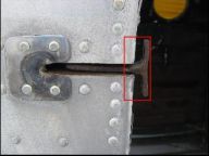
Port Nose Door Hinge
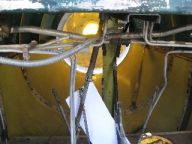
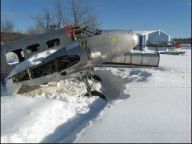
Or, an option could have been to remove the Nose Door itself and fight the hardware from a more advantageous position. Well, the problem there was the snow – it simply wasn’t possible to set up a stable platform to get the Nose Door off.
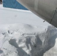
Depth of Snow
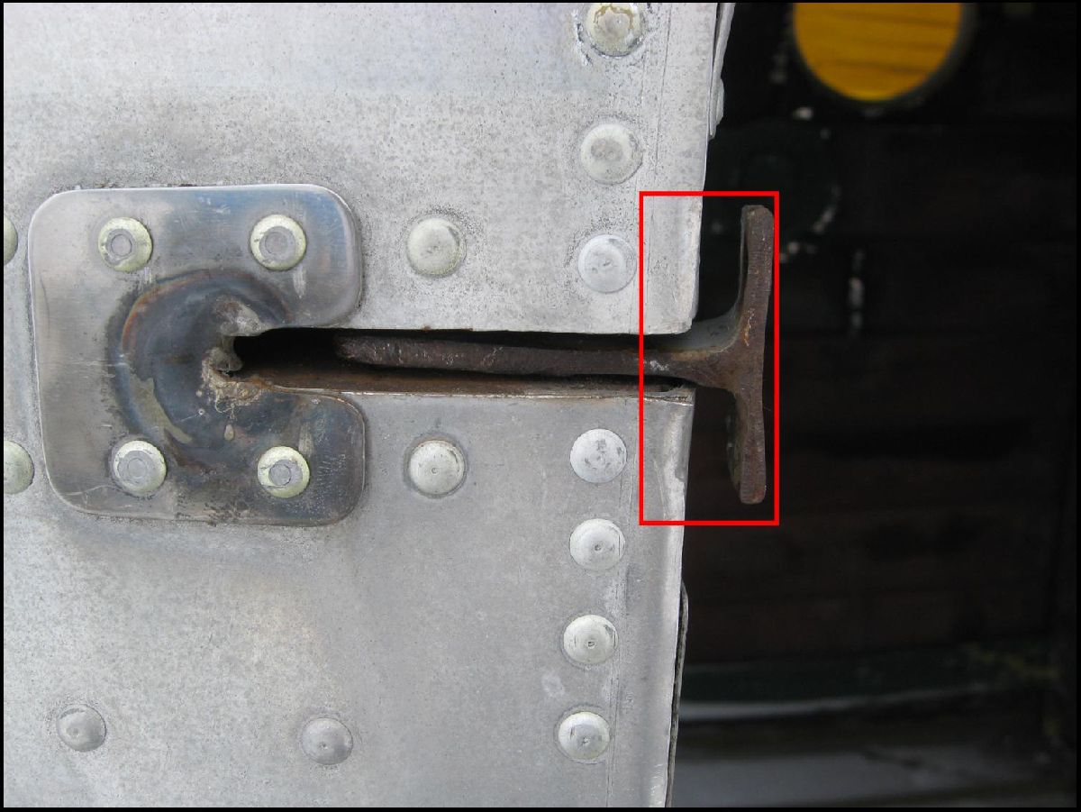
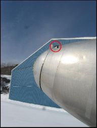
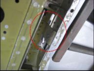
Matter of fact (and looking on the positive side, here) it was interesting to clearly see and identify some potential problems for when the Nose Door will be installed. (Specifically the size of the gap between the Nose Door and the Fuselage.)
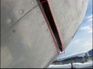
Gap between Nose Door and Fuselage
Preferably it would have been far better to say that we were able to get this tasking completed on this MRP. (Unfortunately, that just wasn’t possible.) What it does mean that when we head back here, with all the recce that we’ve done on the Nose Door (and the potential problems that may greet us), it’s looking more favourable that we’ll get this tasking completed very soon. Ah, well.
Ready for the next MRP with all these parts ready to go!
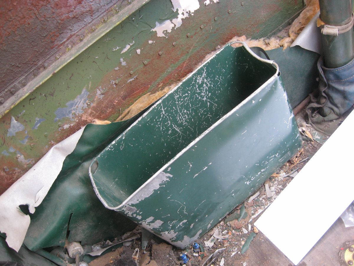
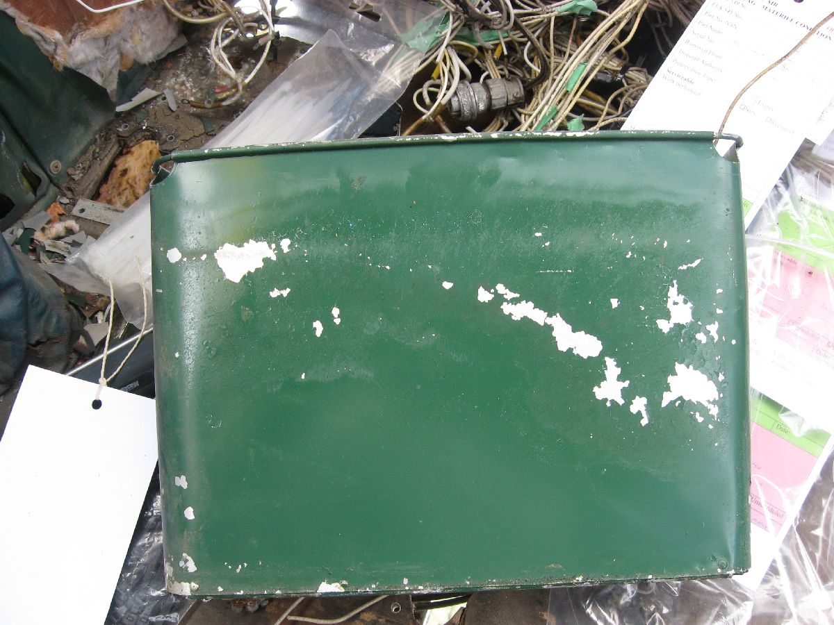
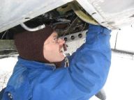
Remove Brake Reservoir
Options – this is something that you really need when you’re working in such a tight area under the Pilot’s Sub Panel area. Thankfully, the Rudder Pedals had been removed – otherwise there would have been just no way that I could have squeezed myself into the nose of the aircraft. (Granted, it would have been much easier to come in from the Nose to work on it.) However, the deep snow (and lack of safe footing) for access coupled with the fact that putting all that weight in the nose (without putting a counter balance in (or on) the tail is a sure recipe for disaster!
More to the point – all that needs to be done for this tasking is this – cap the access points for the lines and remove the mounting bolts. Simple, right?
I capped the lines – and then I started to remove the bolts. (The bottom two were quite easy – and, while the top two had to be drilled out, there really wasn’t much to this. Unfortunately that wasn’t the case.
Trying to Remove the Brake Reservoir
Photo Credit: J. Hudson
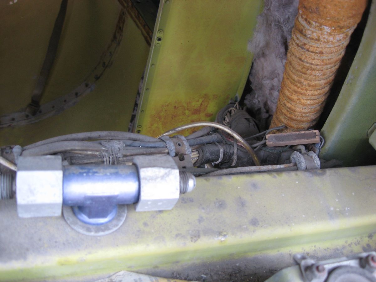
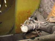
Seeing that there was still a great deal of resistance to removing the Brake Reservoir, I realized that more investigation as to why was required. So – after taking more than a few minutes to get out from under the Sub Assembly area – I found myself leaning on the Nose of the airplane to see what was the hold up.
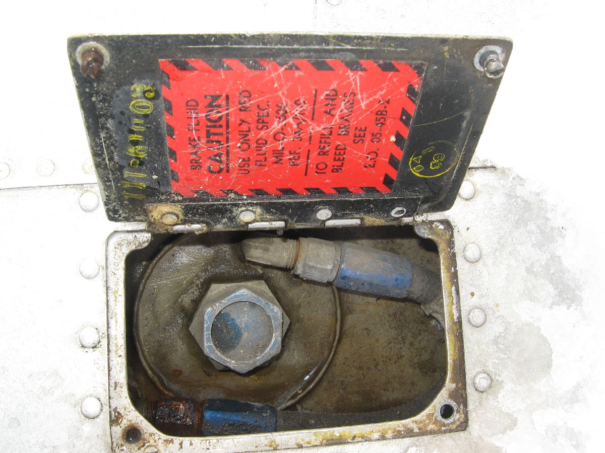
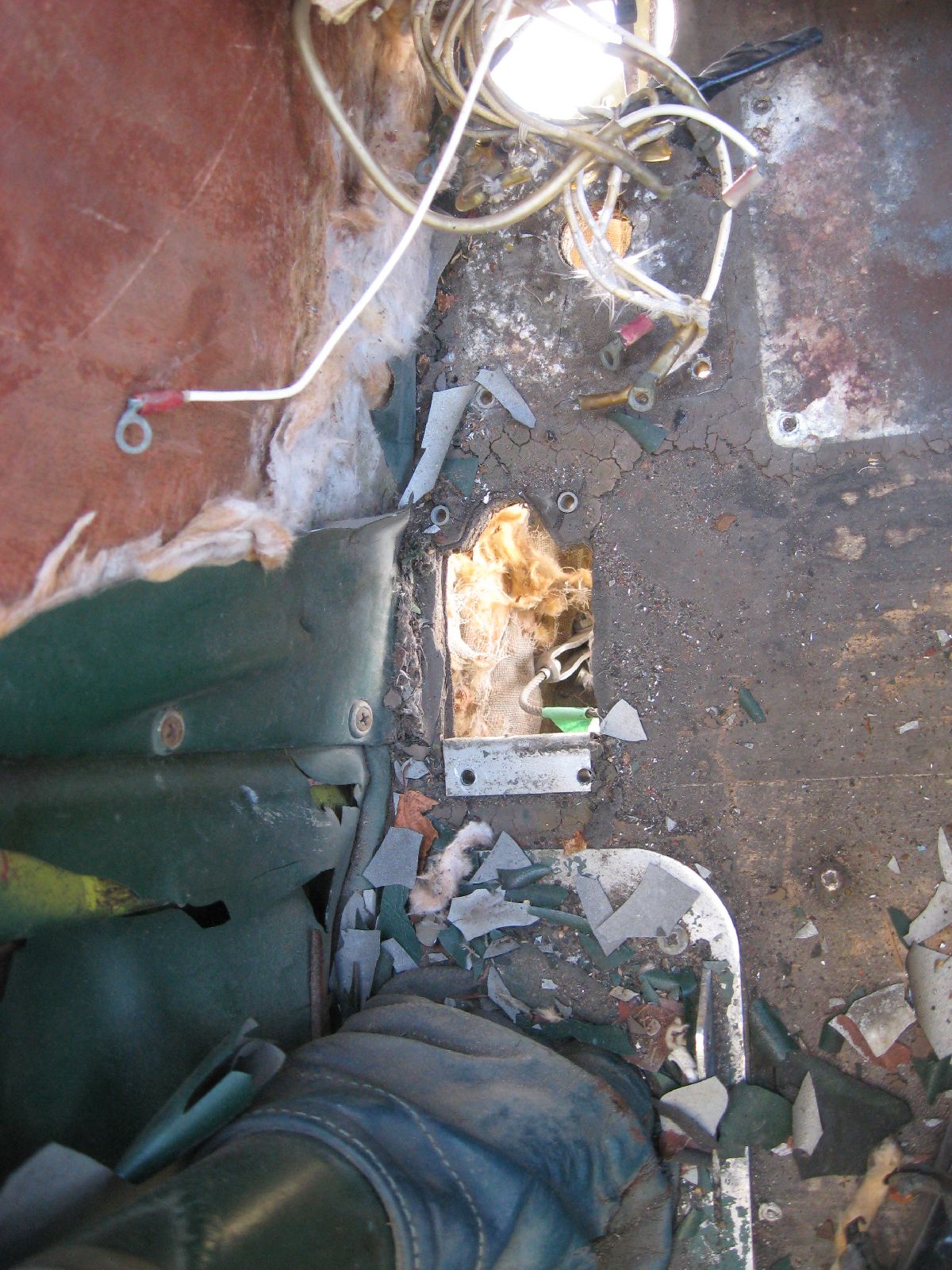
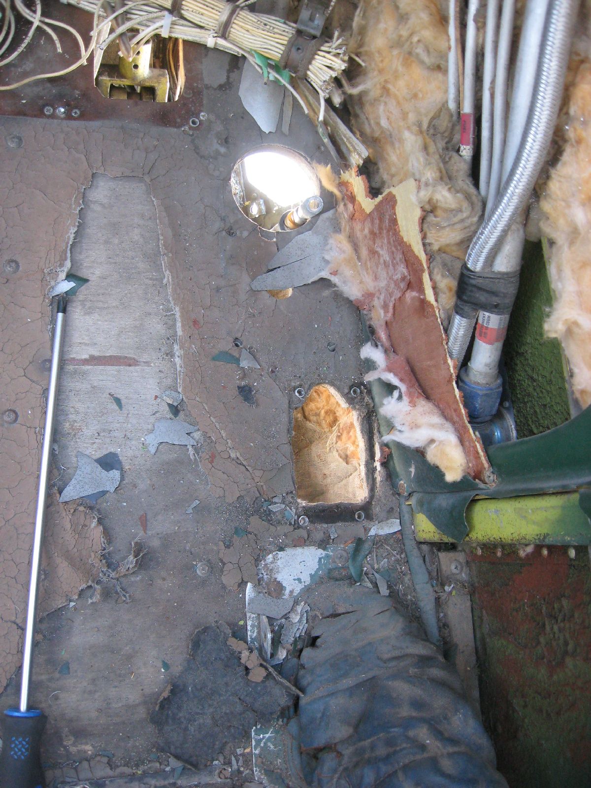
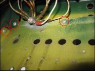
Engineering Orders (commonly referred to as "EO’s") were the RCAF maintenance publications that were used when this airplane was flying for the RCAF. And, what’s interesting about that is – while the books were (at times) quite accurate and a good read – most times the books really didn’t help all that much. What I found when I opened the access panel was interesting at first – an original label from the RCAF EO on the topic of which Hydraulic Fluid to use. (Which was interesting, seeing that I’ve got a listing of the majority of the labels and placards for the RCAF Expeditors – and this wasn’t one of them.)
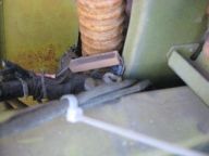
Down past the label, though – that’s what was really interesting. There were two hydraulic lines running down from the top of the reservoir further back into the airframe. (What’s even more interesting is that I didn’t find any mention of them in any of the publications thus far!)
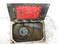
Brake Reservoir with Hydraulic Lines
Usually I’d be pressing on at this point. However, since I had found things that weren’t in the manual – and since I don’t want to force anything to come off for fear of damaging it – I decided to hit to books (and builders blueprints) again to make sure that I was looking in the right direction with regards to this tasking.
So, what this means is that we weren’t able to complete this particular tasking on the MRP, either. What it does mean is that now we’ve got a good idea where to look now (and what to look for) – and next time out we should be able to complete this tasking.
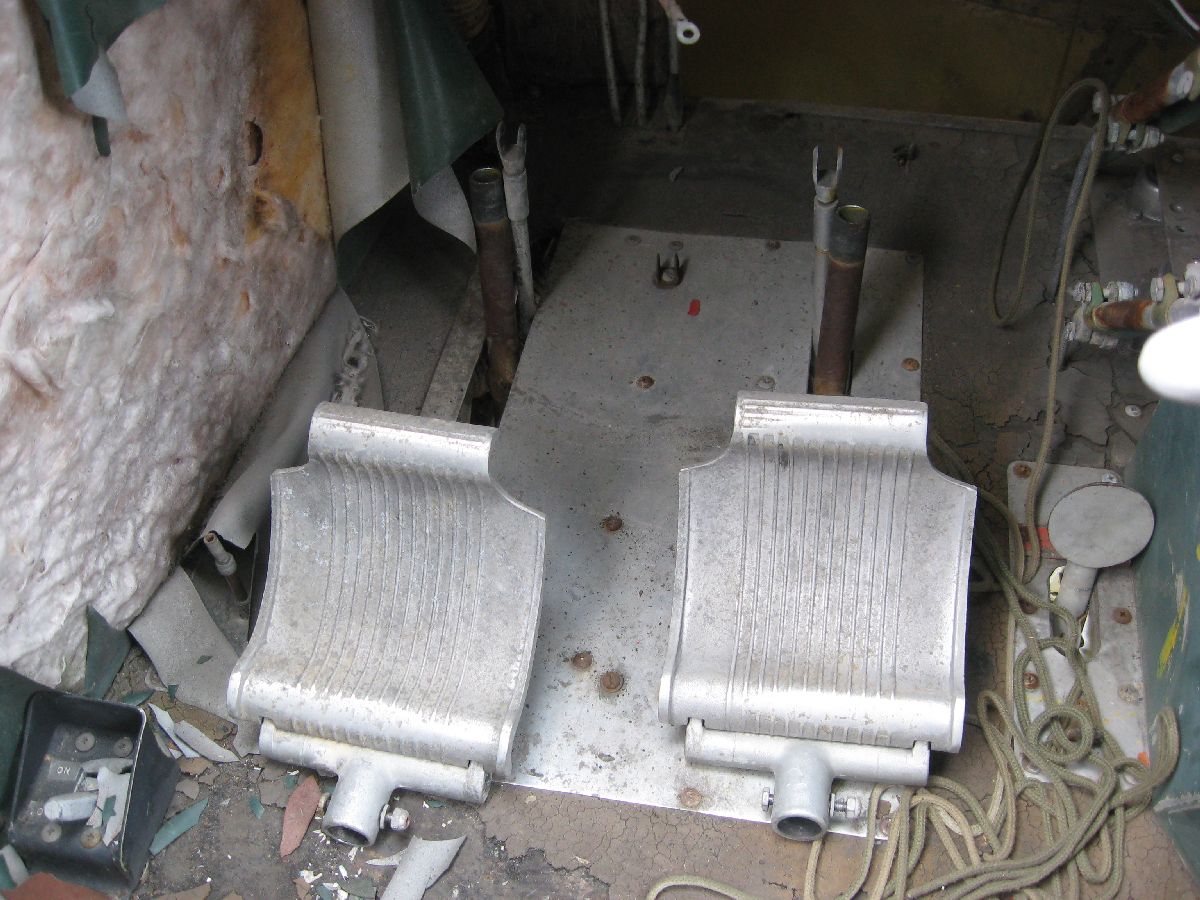
Remove Rudder Pedals and Brake Assembly
Remove Pitot Static System and Cap Remaining Lines
Easier said than done re available space – which is something that I’m sure Hudson is saying having spent most of the week under the cockpit floor fighting really cold temperatures, hardware, and a less than comfortable working position.
Thankfully, it was far easier to remove the Rudder Pedals! The Pilot’s Rudder Pedals came off first, then the Co-Pilot’s. The big take away here – though – wasn’t just the Rudder Pedals themselves. (It was all the work that was done under the cockpit floor that made it possible to actually remove the whole Rudder Pedal Assembly.)
Removing Pilot’s Rudder Pedals
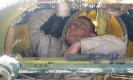
And, for that, Hudson made an invaluable contribution to the MRP by spending his time outside working underneath the cockpit. (As a point of general reference, working under the cockpit floor isn’t the easiest task in the world. You can neither sit nor stand, and there is next to no room to get a tool in there or move around with a great deal of comfort.)
Hudson working under the cockpit
Pressing on regardless despite the lousy weather and the cramped conditions, Hudson was able to remove the majority of the Rudder Pedals and Brake Assembly – and also remove and cap the remaining lines for the Pitot Static System.
Can we say that all of the related Sub Assemblies were removed on this MRP? Unfortunately – and honestly – no. Quite frankly, we were running out of time at this point. (Just to get all of these parts off took up most of Hudson’s time throughout the week.)
Otherwise, if we’d had more time I’m certain that we would have been able to fully complete this tasking. (Having said all of that, most of the PO was completed – which was very difficult in itself.) Something that I’d like to point out here isn’t just the parts removal – but making sure that all the parts are properly labelled so that we know where to put them back when it comes time for the reassembly phase.
Definite progress has been completed on this tasking – which is the main take away for this MRP. And – even better – we now know a great deal more about what goes where (and how to remove it) from under the cockpit floor.
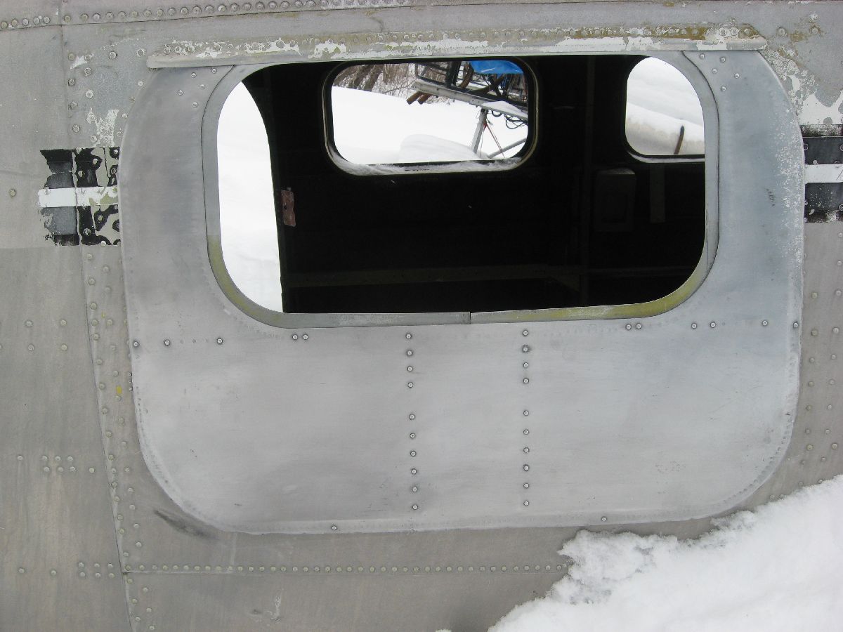
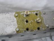
Pre-Fit Emergency Exit Hatch, Main Cabin Door and Door Scuff Plate
Examining the parts is just one of the many problems that you run into when you’re starting a restoration project – that and the relative age of the parts. (While a part may look good initially, it needs to be completely stripped down, cleaned and inspected to really be sure that it still can be used as a Serviceable Asset.) And, as the parts become older, this becomes more of a problem. For example, the part number may match the part manual – and the builders blueprints – but so much time may have already passed with the part being used (or a part that you want to use) results in the simple fact that the part may too old and can only be used now as a pattern to have a completely new part made.
Forcing parts that are this old to do anything at all is a really bad maintenance practise to begin with. (Not only will you probably wind up damaging the part, but the airframe as well.) That was something – in a long list of somethings! - that concerned me when this tasking was started – which is why I really wanted to go slow with the pre-fit of these parts.
Emergency Exit:
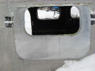
The initial fit into the fuselage

So far so good
Making sure that everything aligns as it’s supposed to.
Old parts or not – I made a point of taking it quite slowly to make sure that everything fit – especially with needing any force. So, as a result of being very careful, I’m happy to report that the Emergency Exit Hatch fits as it should. Now, what’s going to happen to the hatch (which was stripped and cleaned by Jason Dunfield, an ACS Tech that I know) is that it’s going to be inspected and rebuilt with new attaching hardware and a new window. (The thinking here is that – before more resources are put into this part – does it properly fit where it’s supposed to go?)
Until I was certain that this part would find as advertised, I wasn’t certain how easy it would be to find another one. (Not only that - the big worry with this is that the Hatch may have warped over time or simply not be able to be used other than as a pattern.) Thankfully, that’s not the case – and this part can now be restored to Serviceable Status!
Main Cabin Door:
Not forgetting to mention something about the Main Cabin Door, the night before I was to try the Pre-Fit tasking I wanted to make sure that Door was as ready to go as possible. (Not only checking the door over for any damage, but installing as much as possible on the door – at least, temporarily – to make sure that when I would do the Pre-Fit in the morning I would get as close to possible the best results.
Don’t forget - the big issue here is that (when the Main Cabin Door was purchased) a whole lot of parts needed to be re-installed. One of the many parts was the Main Cabin Door Lock and Handle.

Prior to Installation
Having carefully installed both the Lock and Handle – the Main Cabin Door was ready to go for the Pre-Fit.
Installing the Lock and Handle
Photo Credit: J. Hudson
Exceptionally happy with the success of the Emergency Exit Hatch, I thought that the Main Cabin Door pre fit would go quite quickly – boy, was I wrong! Initially, though – it looked quite good.

The Initial fit into the Fuselage
Really quite happy about the fit of the Door itself in the Fuselage – no binding, no rubbing, no wear patterns visible (absolutely nothing, as a matter of fact), I was all set to write this one off as complete – and then, upon a closer look I realized that something wasn’t quite right after all.

Top and Bottom Hinges out of alignment
Exceptionally surprised at the angle that the hinges were on, I (very quickly) realized that the hinges were installed backwards. No problem – I removed them with the intent on flipping them around on the door and then trying again. But then, I decided to see how well the hinges fit.
Size of Gap between Main Cabin Door Top and Bottom Hinges
Potentially, the problem could be where the hinges attached to the fuselage. Failing that, the problem could be where the hinges attached to the door itself. (At least, that was what the initial thought process.) However, after looking at the fuselage – and where the hinges attach, no problems were found there. And, honestly, I was a little surprised about the lack of problem where the hinges attached to the fuselage. (On top of that, I was really hoping that I could find the source of the problem sooner than later.)
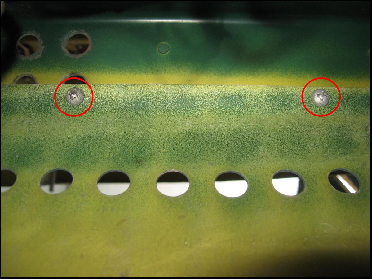
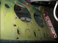
Until I started taking a long look at the Main Cabin Door – and then the problem became quite clear. When I tried to install the hinges – only two screw holes would match up per hinge. (And – even then – the angle of the hinge was really off as well.) So, what this means is that another set of Main Cabin Door hinges are needed – and they have already been ordered.
The source of the problem – hinge would only attach at these points.
Truthfully, I would have preferred to have a successful conclusion of this tasking but that’s why I was doing the Pre-Fit so that problems like this could be identified right now. That way, when the Main Cabin Door has to be installed (and signed Serviceable), the tasking will be completed that much faster.
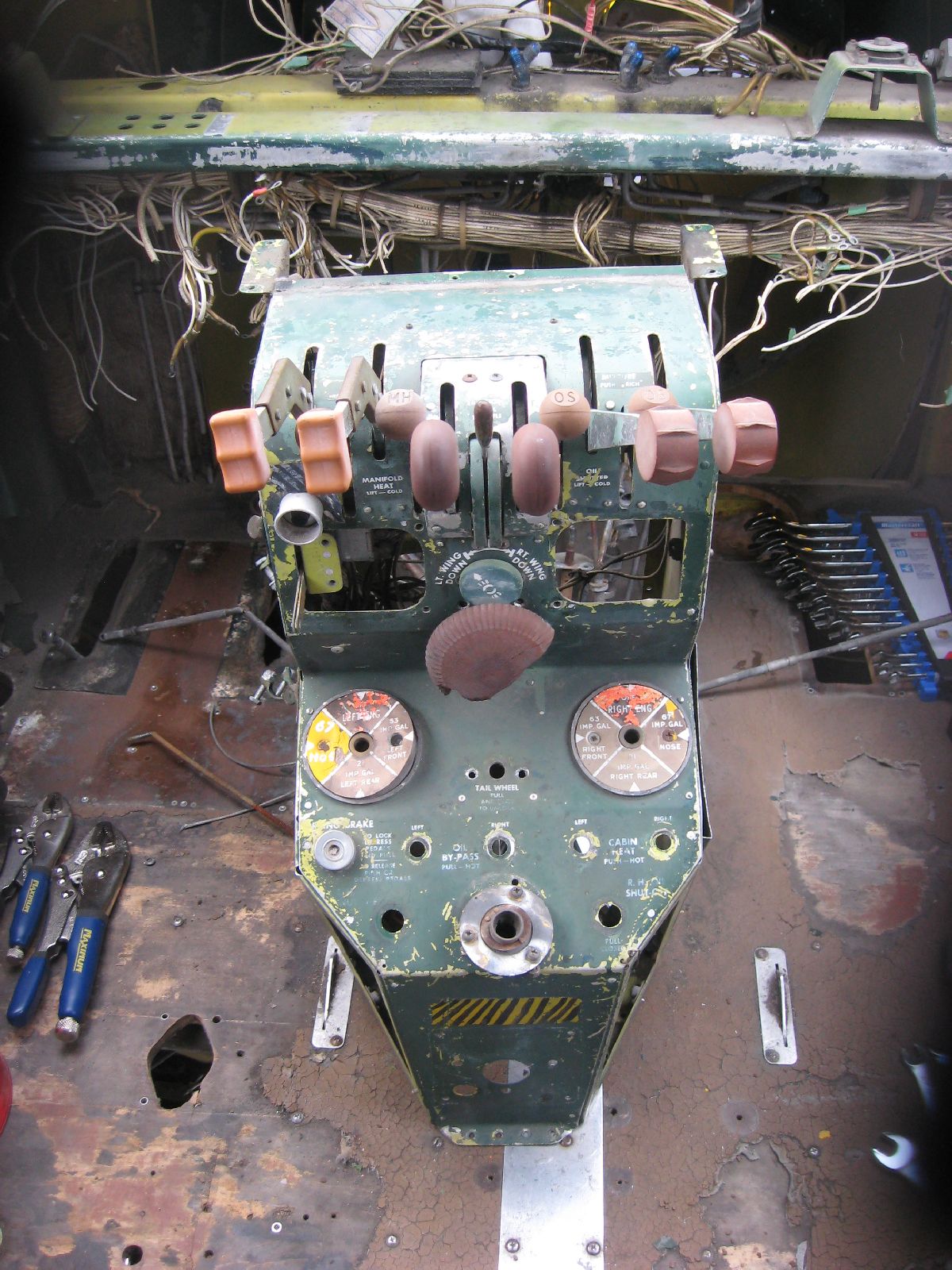
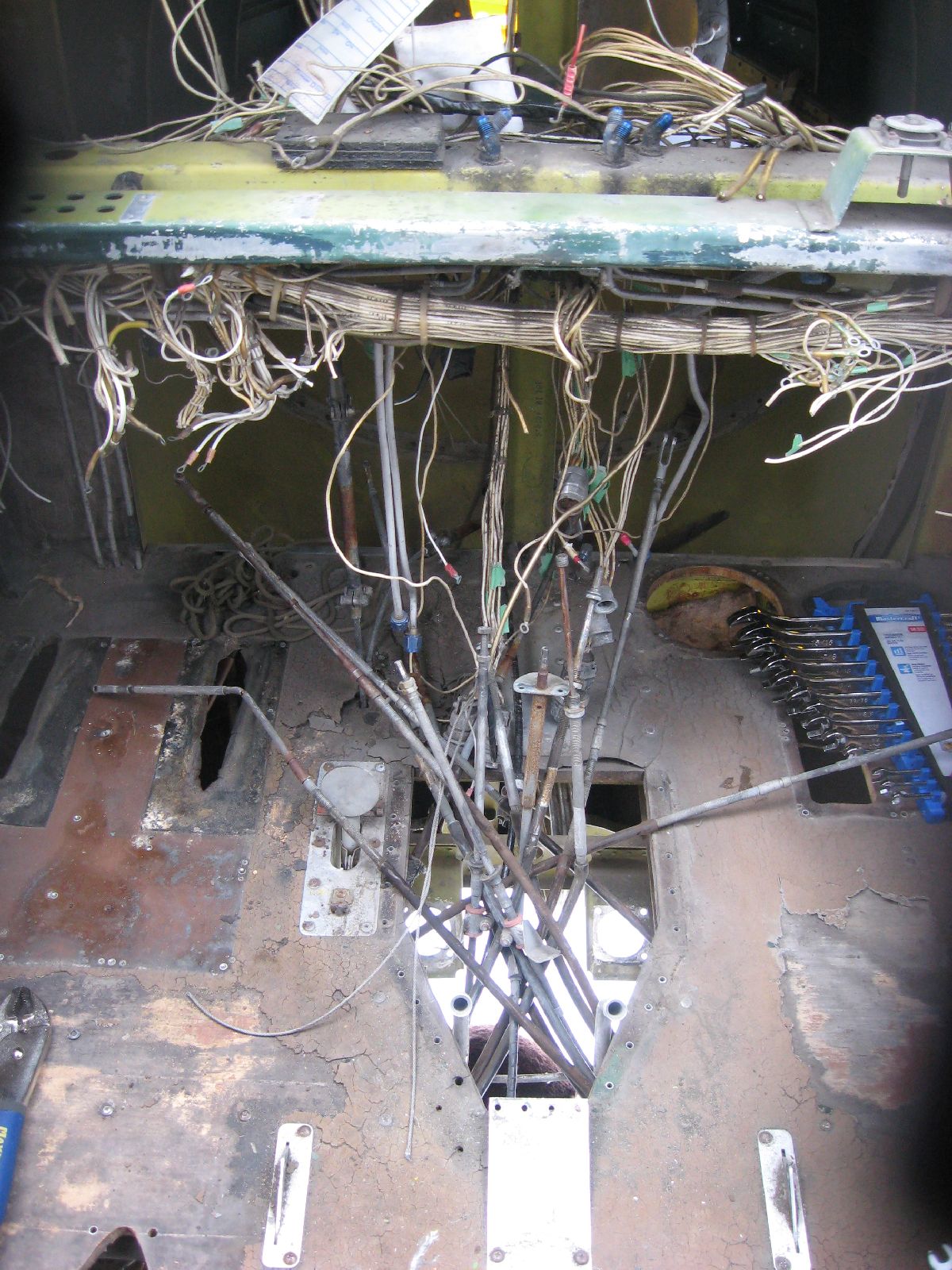
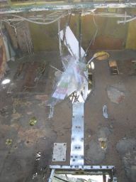
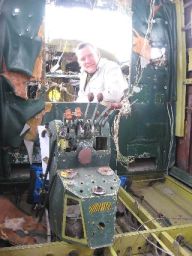
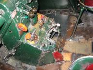
Remove Centre Control Pedestal
One of the major taskings that really needed to be completed on this MRP was the removal of the Centre Control Pedestal. (More importantly, removing the Centre Control Pedestal in such a way that: neither the Teleflex cables behind it, the mounting screw holes in the Cockpit or the Cockpit Floor would be damaged throughout the removal process.) Quite the tall order, when you think about it!
Now, the first step – logically – would be to try and find just where all of the bolts are that hold the Centre Control Pedestal are to at least try and get an idea of how many bolts are holding this piece of kit down. (And here’s where the problems start – you really had to look in very tight corners and behind a lot of equipment to at the very least see where the bolts are.)
Exceptionally cold and tired at this point – and, honestly, not having much of a sense of humour for the designer of the airplane – all of the bolts were found and slowly started to be removed.
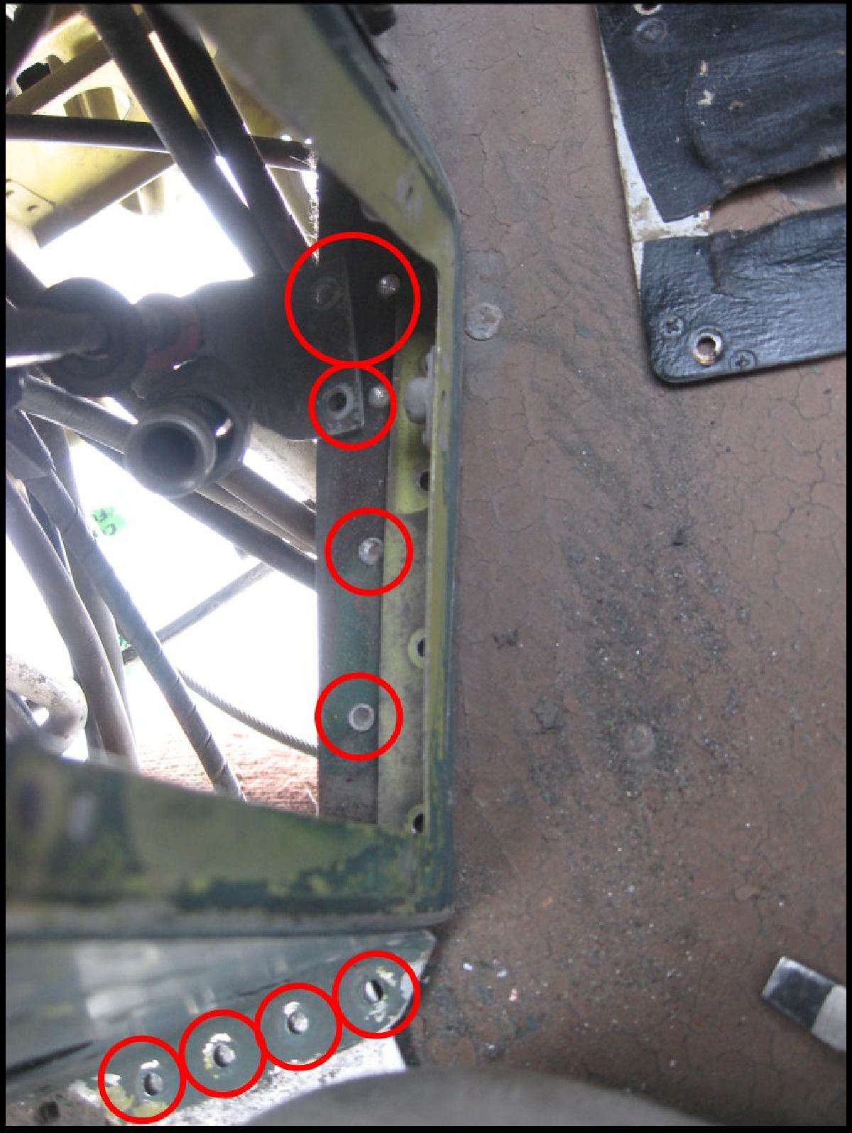
Here are the more obvious places for the bolts. But just seeing where the bolts are doesn’t mean that it’s that much easier to get a tool on them to remove them.
Out of bolts to remove at this point, I honestly thought that this tasking was completed. (Boy, was I wrong!) You see, I had forgotten about all the Teleflex cables behind the Centre Control Console.
Not the thing to forget about – especially since there are so many cables in such close proximity. (And, all of them held on to their proper lever with a cotter pin.) That meant that I (somehow) had to get in there with tools to try and get that cotter pin out – and without damaging the Teleflex Cable.
You’d think that I’d have learned my lesson at this point with regards to the removal of the Centre Control Console – just when you think you’ve got all the bolts out, all the cotter pins out, everything possible that could connect it to the airframe – there is always something more.
Only, what was holding it on now were the lower Teleflex cables – the ones that weren’t attached with cotter pins. (Ordinarily, it would be quite easy for these cables – but because they hadn’t moved in almost 40 years, that meant that an easier tasking got that much harder all of a sudden.)
Using more patience, all the cables were disconnected (very carefully disconnected), and all other bits and pieces that were holding it to the cockpit were eventually removed – to produce a successful completion of the tasking!

It’s harder than it looks to remove, believe me!
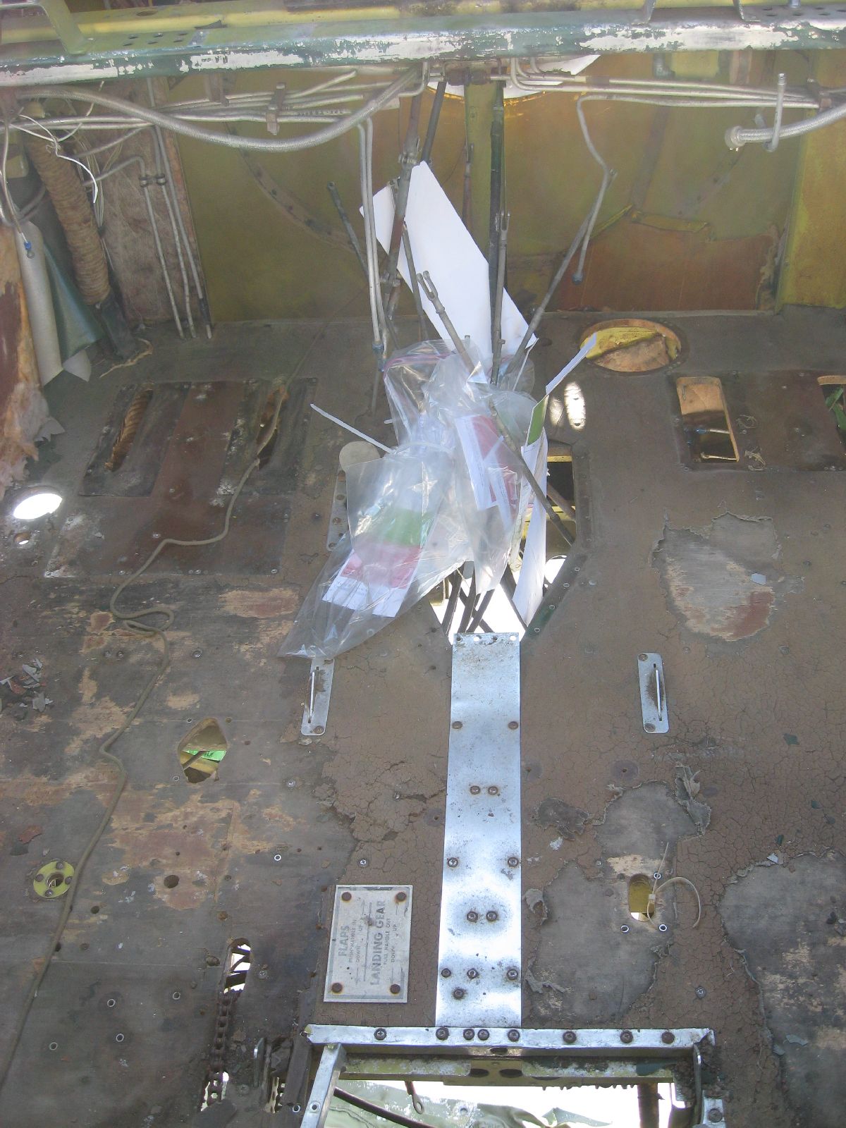
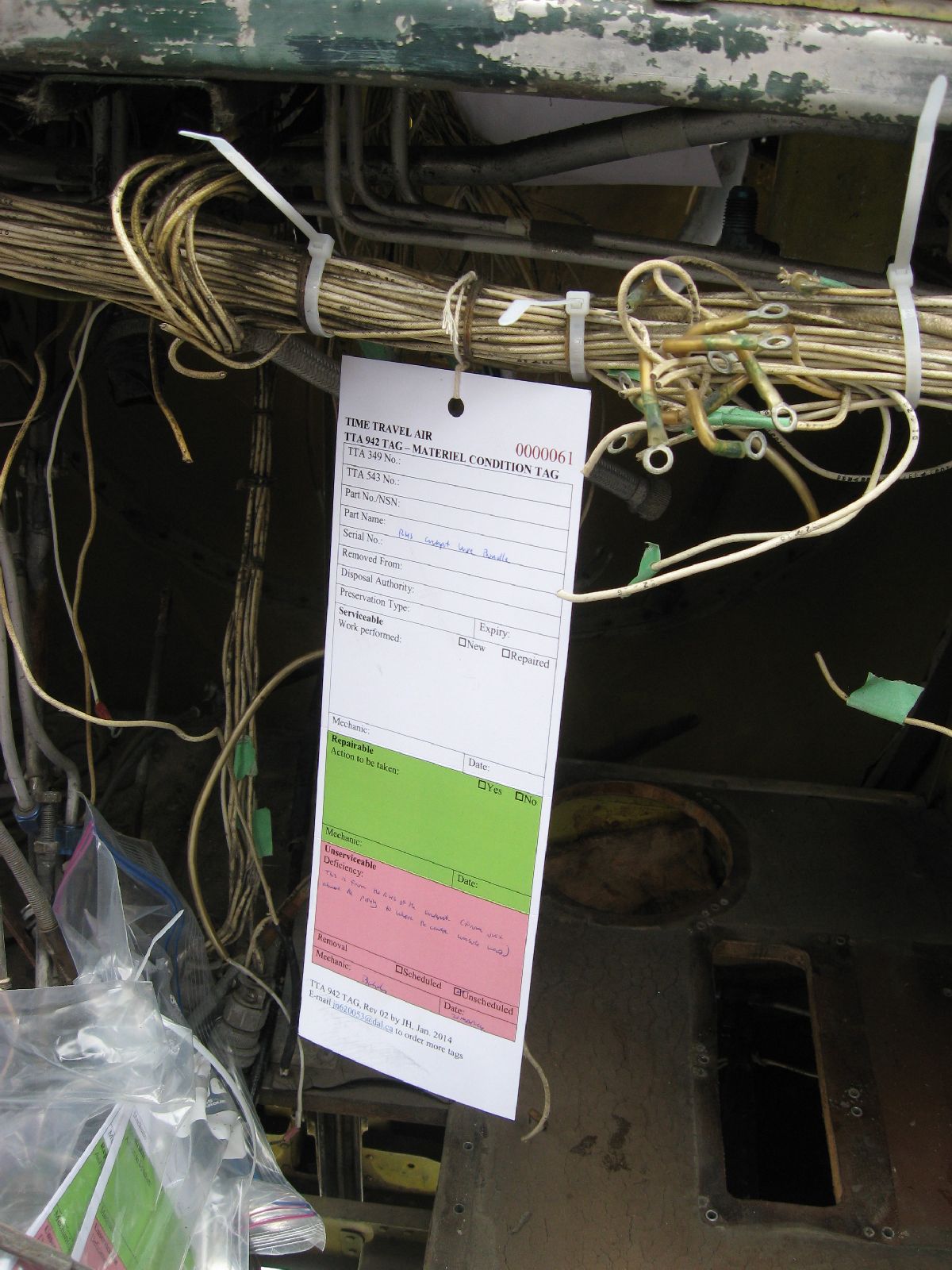
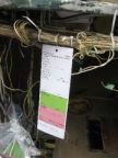
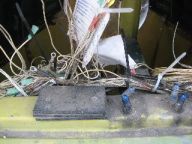
Really, that should have been it for this tasking, right? No more work? Close – but not quite. All the Teleflex cables that were disconnected had to be tagged and very carefully identified as to what went where. After that, all the tags were carefully wrapped in plastic to try and protect the tags as much as possible from the elements.

Before and after photos of labelling the Teleflex Cables
First and foremost, though – this major (and rather difficult) tasking was completed! No collateral damage done to the Centre Control Pedestal, the cockpit or the cables – for which I’m very grateful. (Now the Centre Control Pedestal can be completely dismantled and overhauled far easier.)
Successful removal!
Photo Credit: J. Hudson
Remove Sub Panels
Boy, after removing the Centre Control Pedestal I would have thought that removing the Sub Panels would have been a whole lot easier.
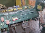
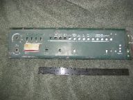
Pilot’s Sub Panel (Before Removal)
Photo Credit: J. Hudson
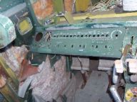
Co-Pilot’s Sub Panel (Before Removal)
Photo Credit: J. Hudson
Man, was I ever wrong!
Instead of 16 bolts that would easily come out with minimal effort – what happened was the exceptionally careful application of a power drill (to drill out most of the rusted solid hardware) plus a bit of torque on the screwdriver and some luck – to get a very drawn out and lengthy procedure to remove what should have been a fairly simple tasking. (What made things even more interesting was the fact that there weren’t any anchor nuts on the back of those bolts – you had to somehow find a way to get a wrench in there and hold the nut.)
Underneath the Pilot’s Sub Panel – the first 7
Underneath the Pilot’s Sub Panel – the next 7
Simple it wasn’t – but in the end it did work out. (Even though a surprising amount of the cockpit had to be dismantled so that I could even find the bolts – never mind remove them.)
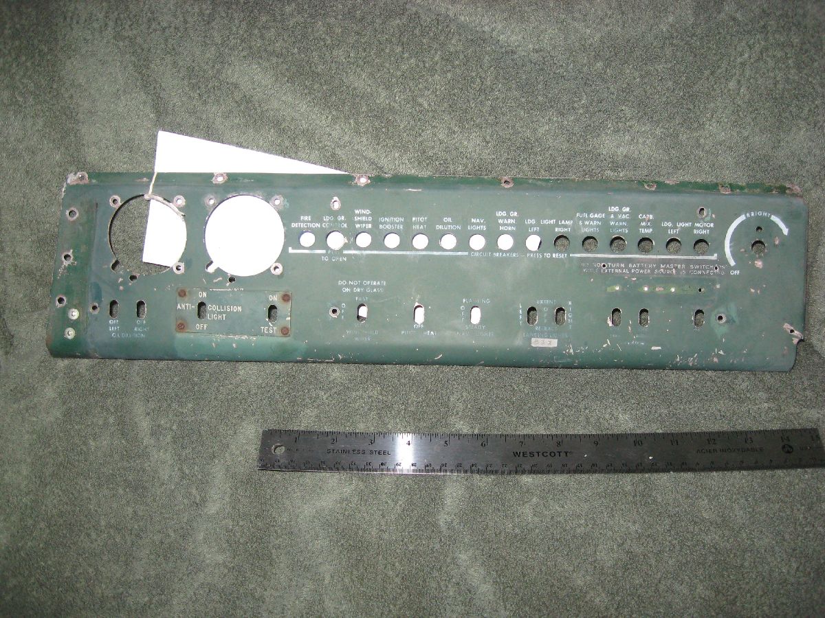
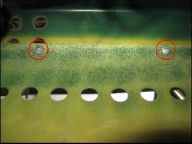
Seriously, though – this tasking was also completed and the panels have been removed. (Why do that, you wonder?) Well, the Panels were showing signs (in a couple of spots) of cracking – and one panel continued cracking past the stop drill. That plus the fact that I would like to get a stencil made of the markings – seeing that we don’t have a blueprint that lists the specific RCAF markings – meant that in the long run it would be better (and safer) to remove these panels now.

Pilot’s and Co-Pilot’s Sub Panel – Post MRP Photo
(Damaged areas circled)
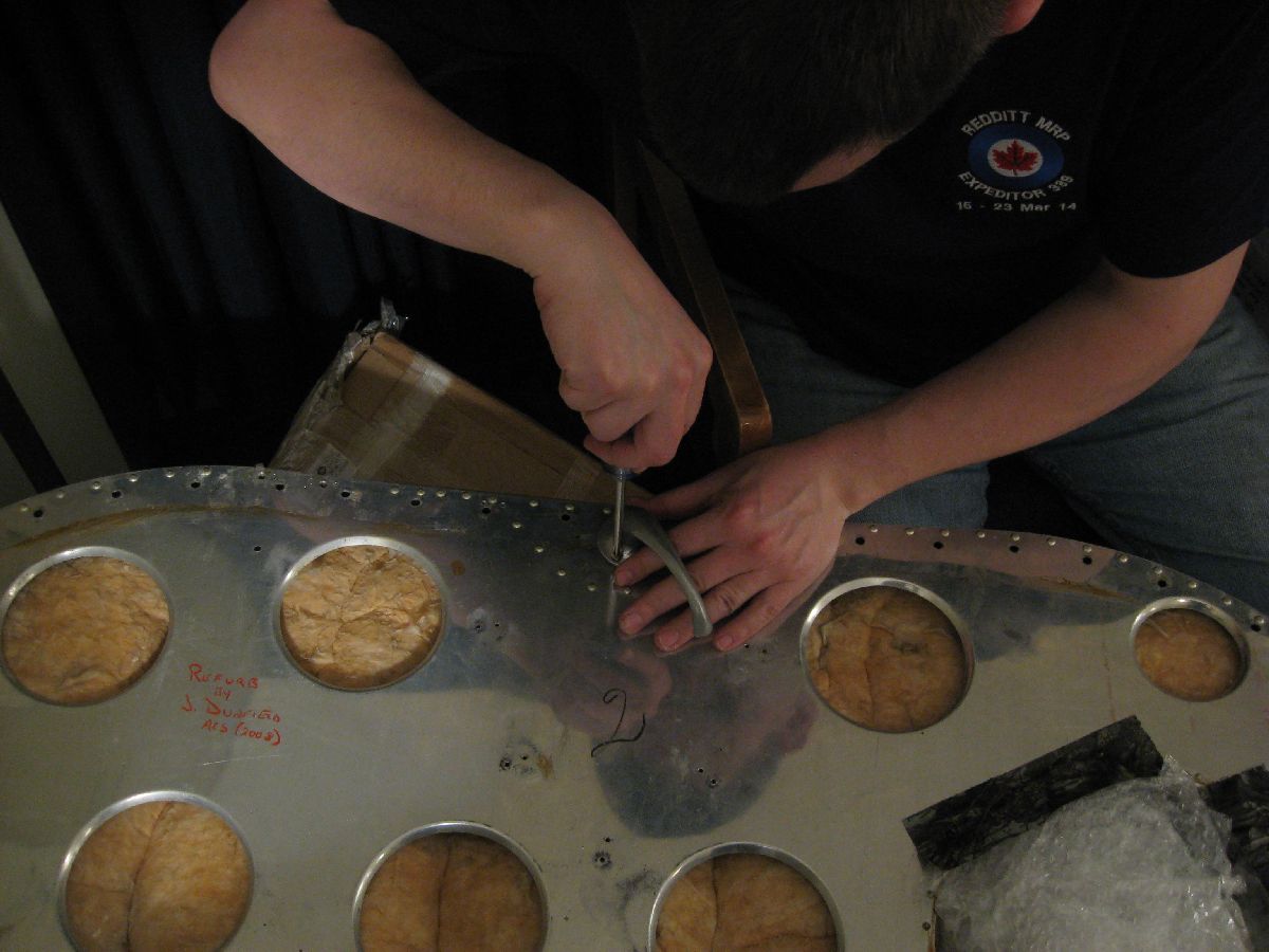
Remove all Electrical Wiring
You’d really think – at least by now, considering all the heavy duty problems that we had thus far with regards to removing the Centre Console and Sub Panels – that I’d be thinking about calling it a day at this point. Realize that I’ve gotten as far as I can go – and kick back, satisfied with what I’ve been able to do out here.
Occasionally, I do listen to reason – and especially I listen to reason right before starting a major tasking right after (actually, quite literally right after) finishing two really hard taskings.
Unfortunately – this wasn’t one of those times. (So, I charged ahead into this tasking of carefully removing all Electrical Wiring.)
Pointing out a few things with electrical, one thing that must be kept in mind is the fact that you really need to trace where each wire is going – and you must have the gauge. Well, in MRP 2013 I tried (rather hard) to put together map of what went where – and I tried to get the gauges. While I did have some limited success on that MRP, I wanted to build more of a complete picture.
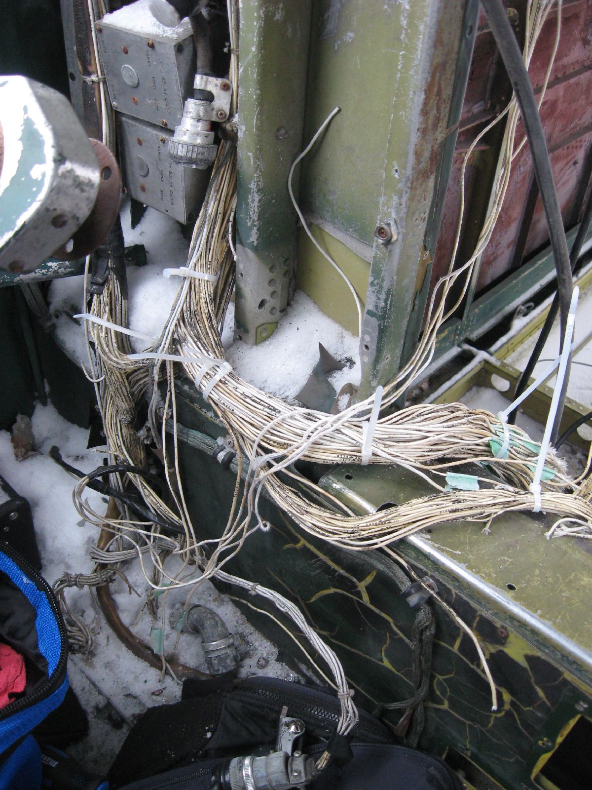
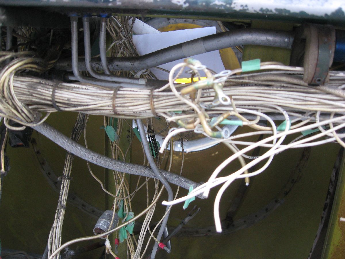
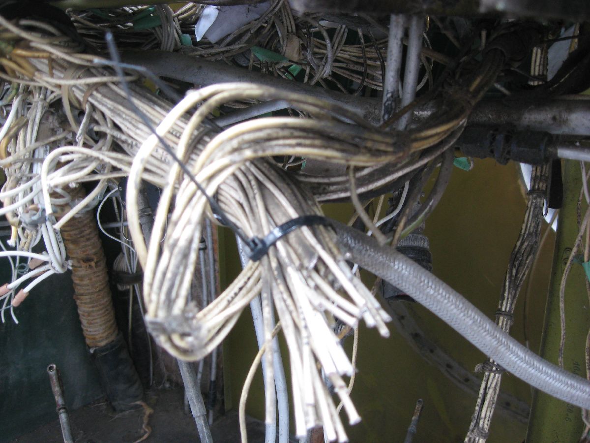
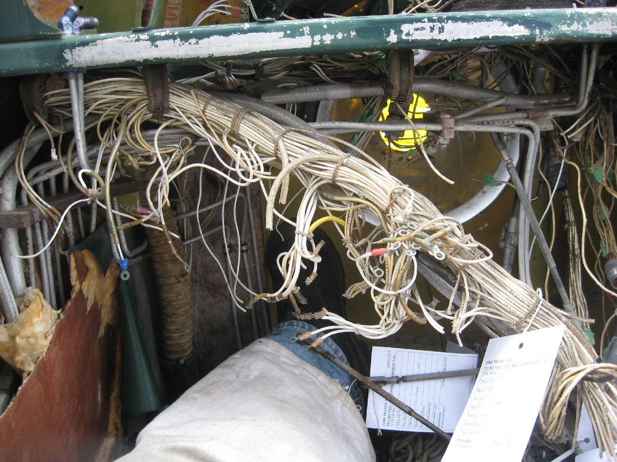
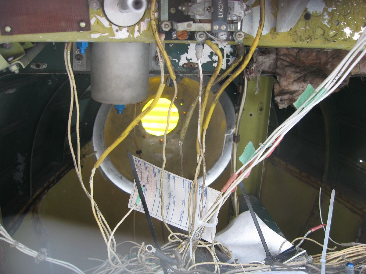
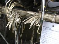
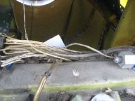
Rather, large bundles of wiring needed to be removed from the cockpit to build up that complete picture. (And, that was something that I wanted to do during MRP 2013 – but, thankfully, I got my chance on this MRP.) So, that’s what I did. I made a point of carefully – very carefully! – labelling each and every wire bundle (plus taking a ton of photos while doing so, as you can see) before I cut the bundles and removed them. Please note, removing bundles like this isn’t something that I was taking in any way lightly – I can appreciate just how much work went into all the electrical wiring that I was cutting. However, something to keep in mind is the fact that the wiring is original to 24 JUL 52, it’s quite heavy (because it’s old), and large portions of the wiring had already been removed due to poor maintenance practises and component removal. I would have preferred to say that I was able to remove all electrical wiring in the whole airplane – after all, that was the tasking! However, the cockpit is almost cleaned out – so I’m going to call this tasking well on it’s way to being completed.

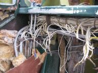
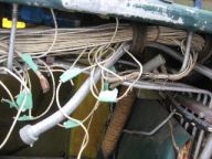
Before the removal – a careful look

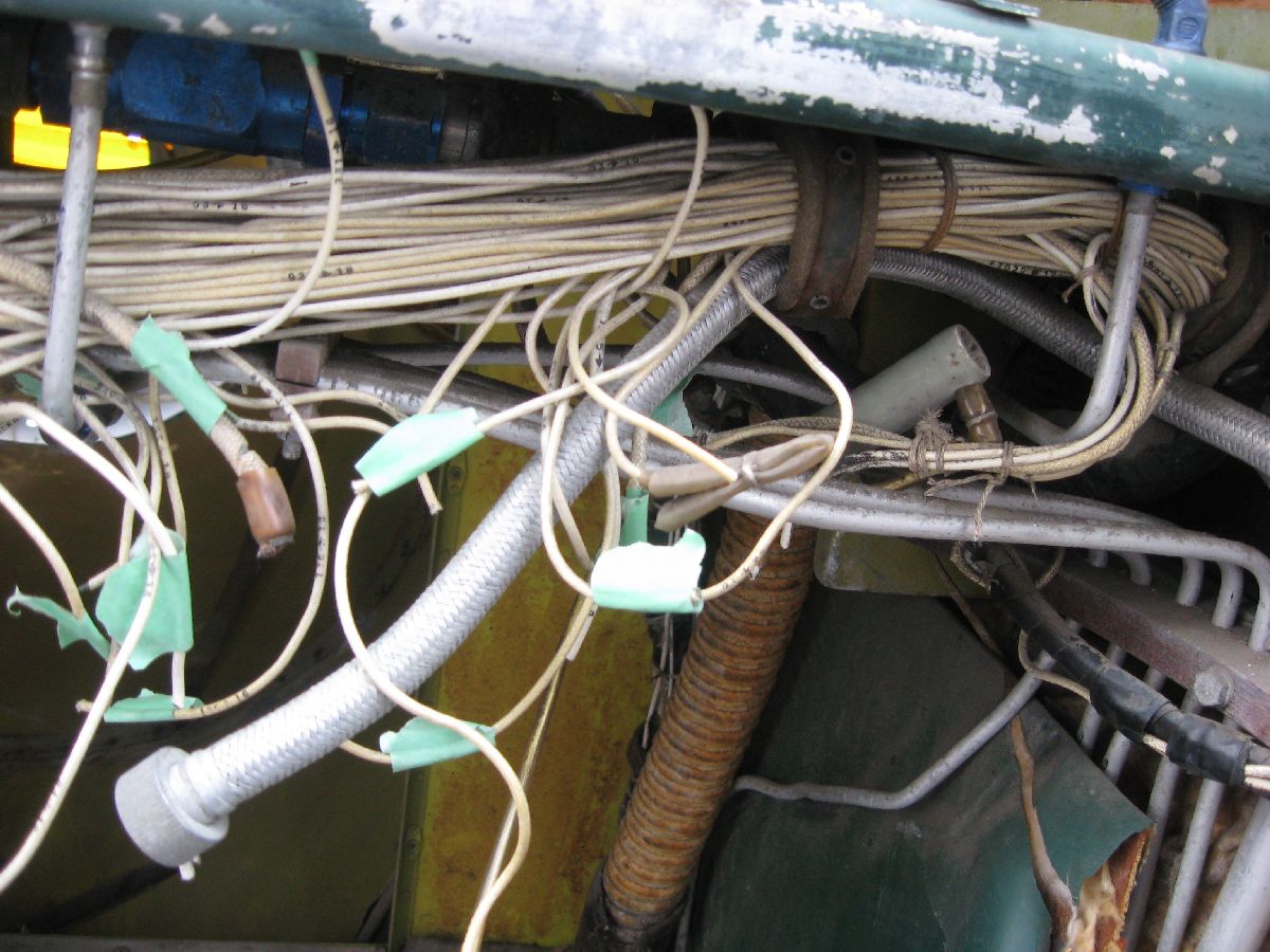
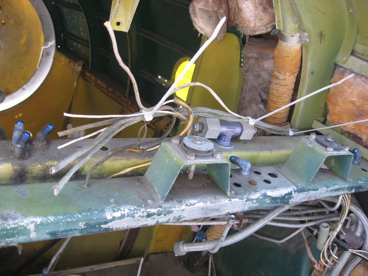
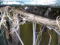
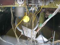
Starting the removal of the first wiring bundle – labelling and the first cutting of the wires
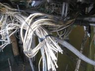

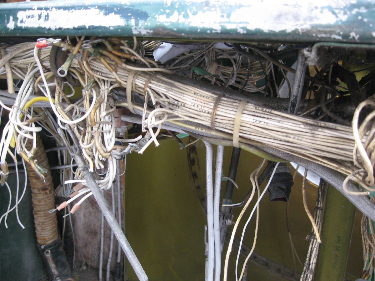
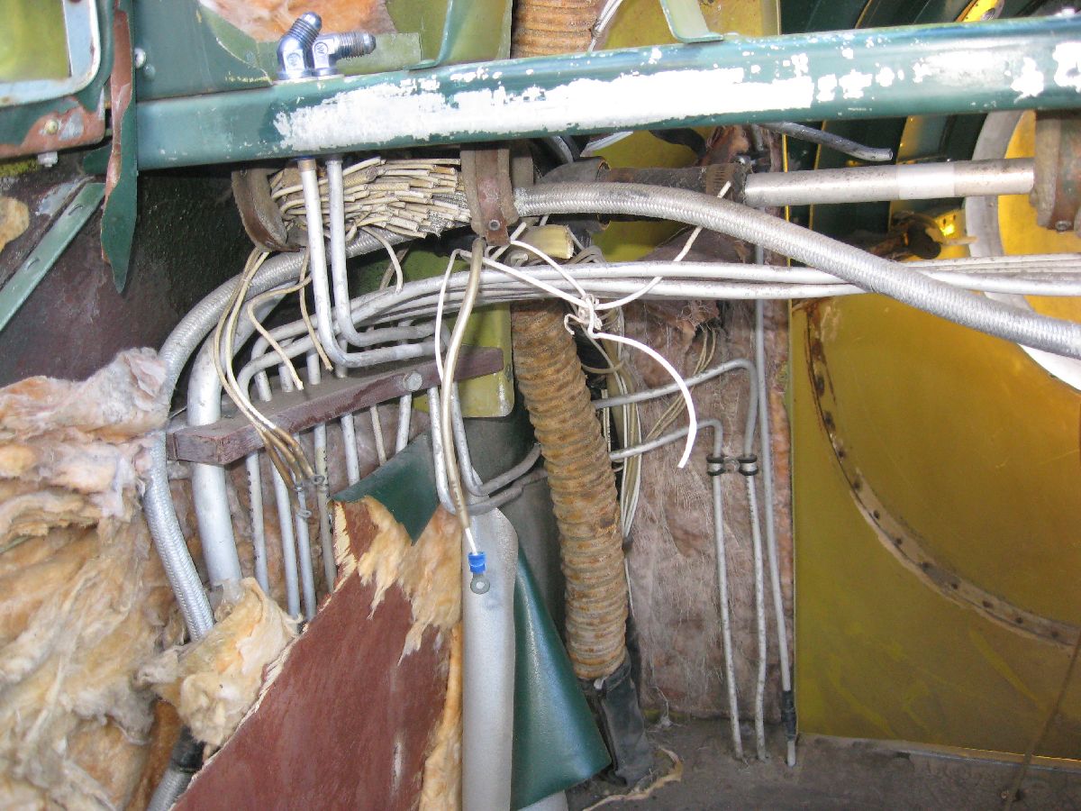
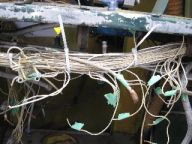
After the first cut – and more detailed photos of the second wire bundle

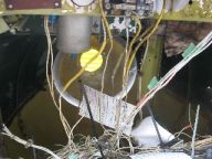

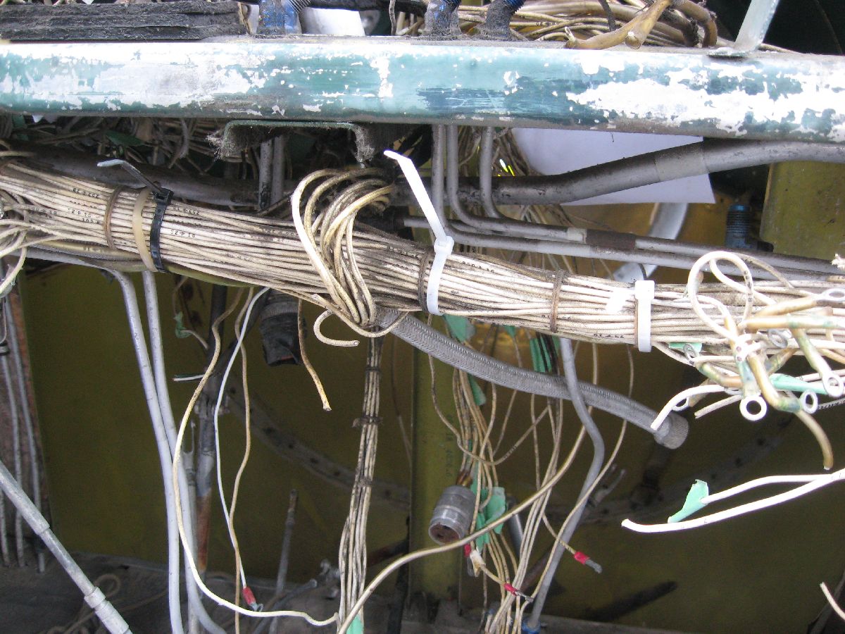
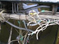
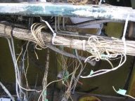
More details photos of the wiring bundles


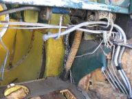
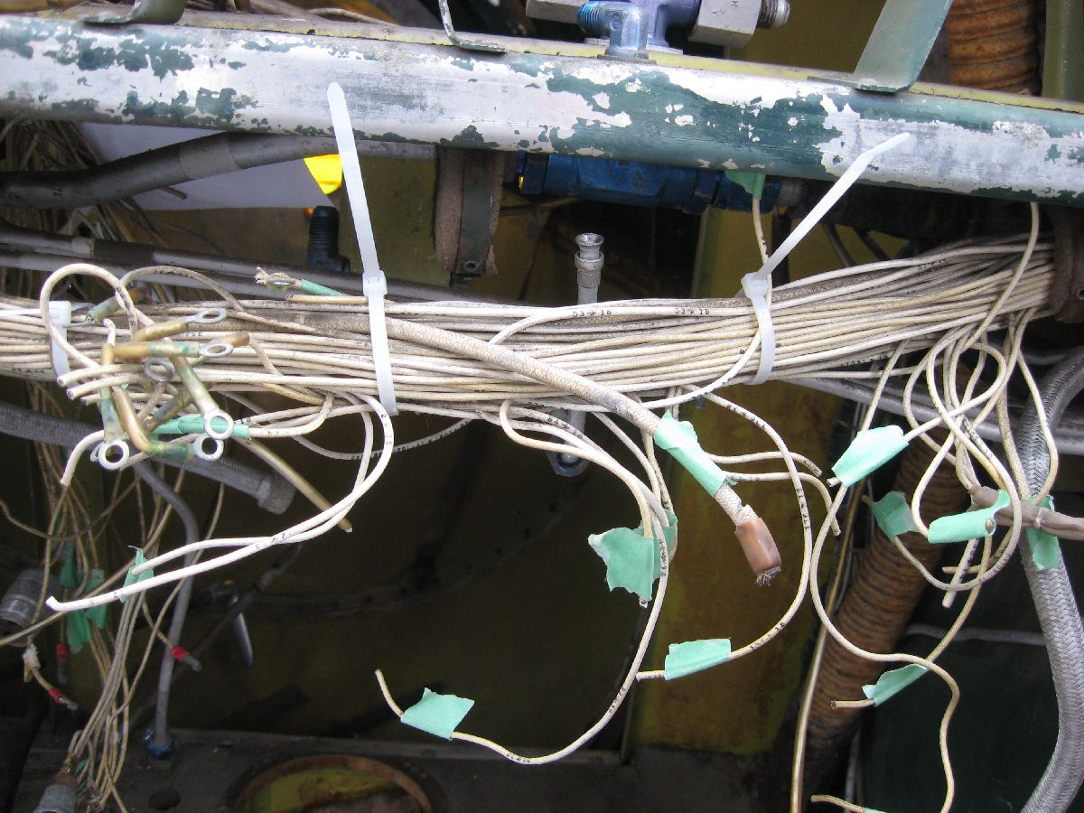
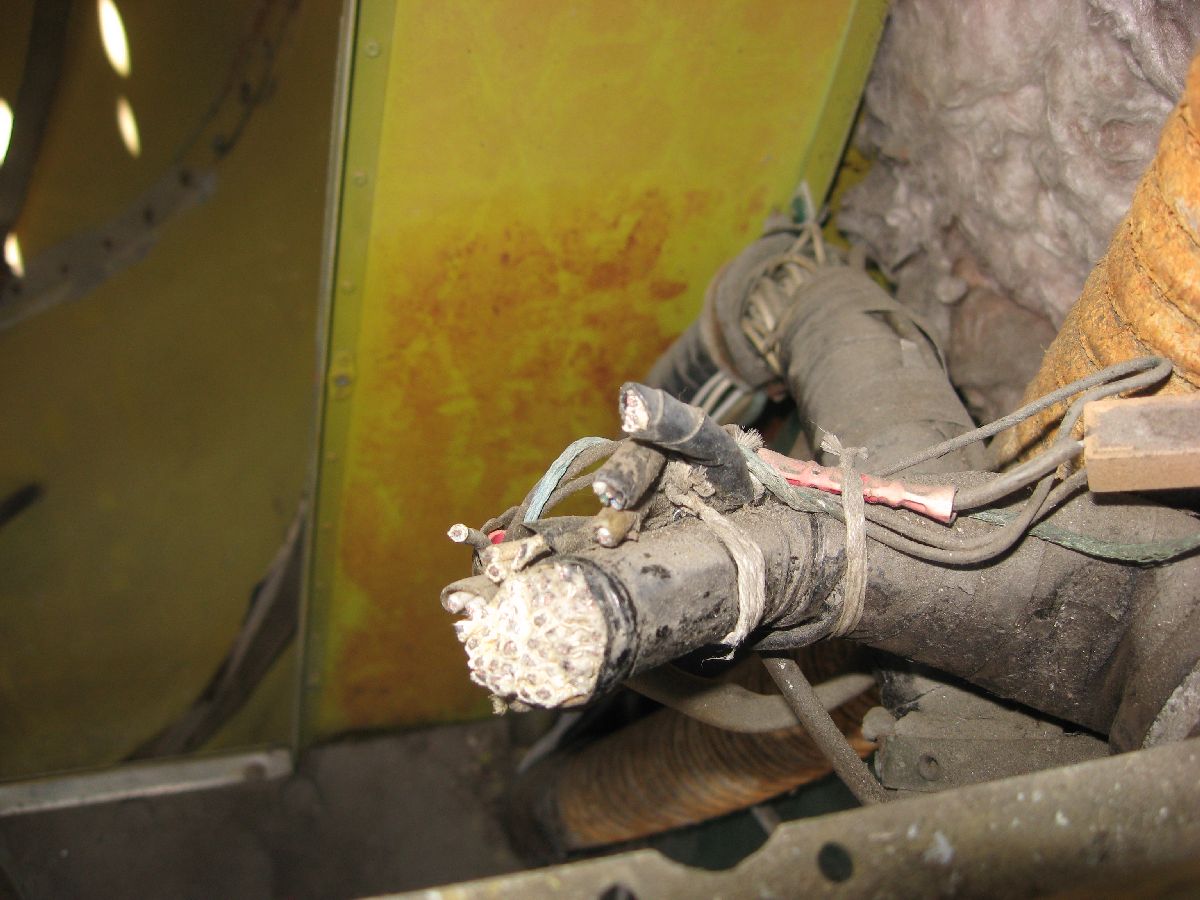
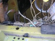
Close up of a cut wire bundle – and after all the wiring has been removed
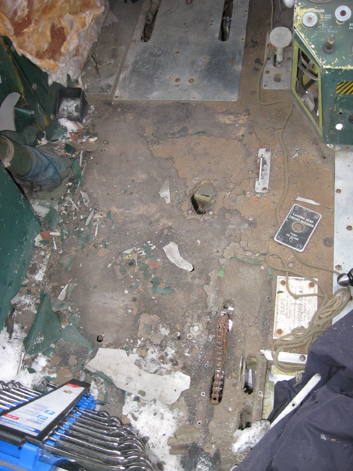
Remove Remaining Parts from above Cockpit Floor
Often it’s has been said that, “It’s good enough – let’s stop for now.” However, that just wasn’t possible on this MRP, because there was simply a lot of taskings to do. For example, on this tasking the following equipment was removed from the Cockpit Floor. (The idea being that we’re getting ready to remove the cockpit floor completely and the equipment that’s attached needs to be removed.)
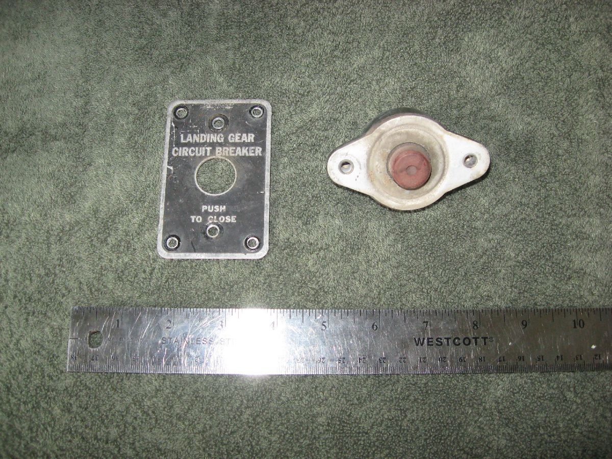
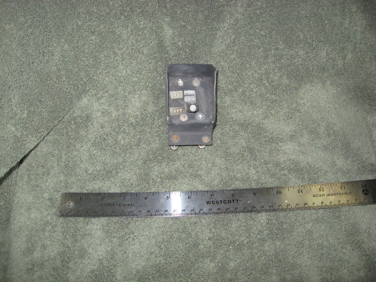
Landing Gear Circuit Breaker (CB)
Understandably, I was quite relieved that this was rather simple – 4 screws and the CB (and placard on the floor) was removed. (….considering all the grief that the attaching hardware was giving us on the MRP….) The big take away with the removal – the “so what”, if you prefer – is that the electrical equipment is old and it really needs to be replaced. (That’s why it has been removed.)
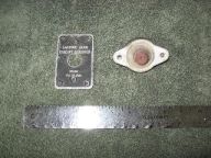
Landing Gear Placard and CB – Post MRP Photo
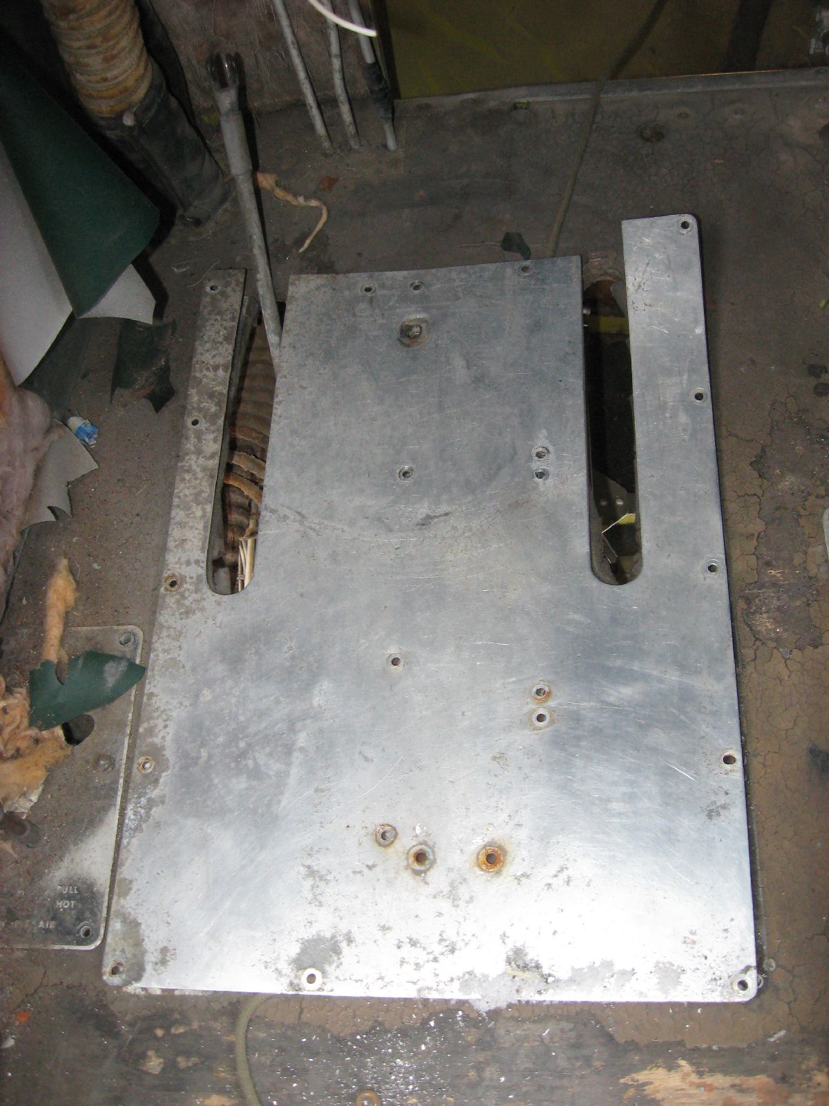
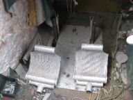
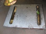
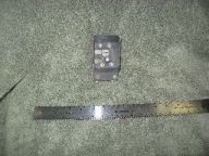
Pilot’s Scuff Plate
Defined simply as “Plate Assembly – Pilot Rudder Pedals Floor”, or – to be honest – a piece of sheet metal that’s been trimmed and attached to the floor to protect the floorboards from being scuffed too much, it’s simply the next piece of kit that needed to be removed. I wish that I could say that it was easy – but thankfully it wasn’t too much of a struggle. Now, why was it removed if it’s only sheet metal – and corroded sheet metal at that? Simple – I don’t have the blueprint for that. So, what’s going to be done is very specific measurements will be made from the scuff plate and – not only will a blueprint be created – but the replacement part will be created as well.


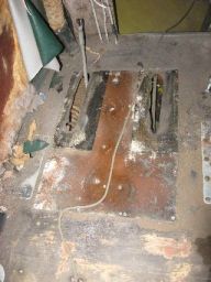
Pilot’s Scuff Plate being removed
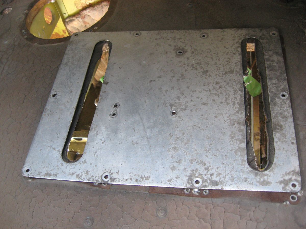
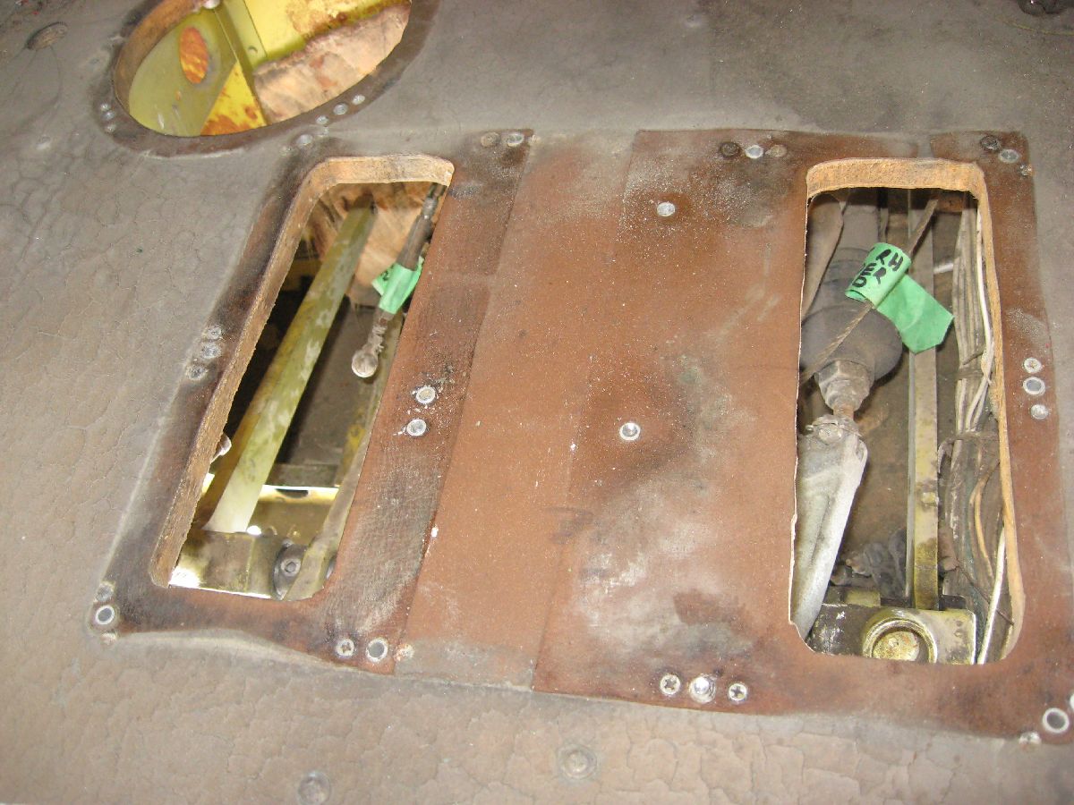
Co-Pilot’s Scuff Plate
On the other side of the cockpit, the “Plate Assembly – Copilot Rudder Pedal Floor” needed to be removed as well. (Same reasons – no blueprint – and a replacement part will be made.) Granted, these two parts are strictly sheet metal – but I really want to do this restoration correctly.

Co-Pilot’s Scuff Plate being removed
Map Case
From the standpoint of importance, it’s not that hard to remove it, but if you look fast you’ll miss with regards to where the component in question is. (Left hand side of the cockpit – close to the bulkhead and right behind the Pilot’s Control Column - if you look down, you’ll find the Pilot’s Map Case.) Seeing that the goal is to get as much of the parts off of the Cockpit Floor – and thankfully, this piece of kit didn’t give me too much grief – it was removed fairly easily.
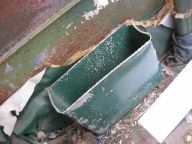
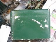
Map Case – Before and after being removed
Generator Circuit Breakers (Port and Starboard)
Young and easy to remove these parts weren’t – let me tell you! What made this even more interesting (with regards to removal) is that this was an RCAF Modification (specifically EO 05-45B-6A/240) that was installed 15 OCT 68. (That meant that it was far harder to get off than just the usual 4 screws.) With a great deal of patience – and a little luck – we were able to remove both the Port and Starboard CB’s.

Generator CB’s right after removal – and Port CB (Post MRP Photo)
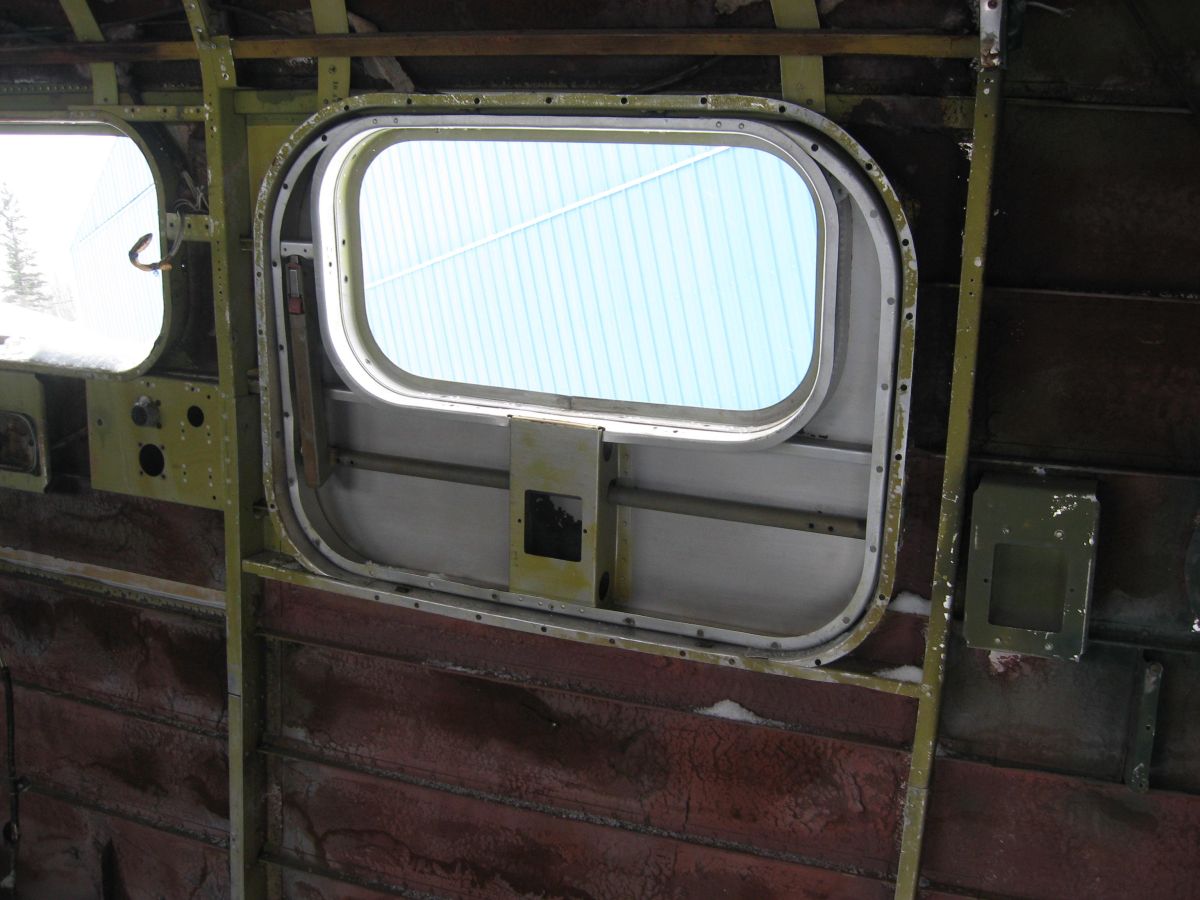
Cockpit Flare Mount
Only a quick tasking – thankfully – but that doesn’t mean that it’s any less important!
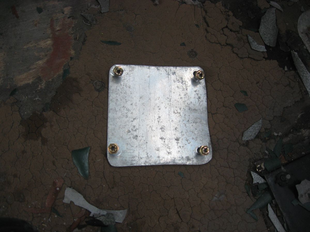
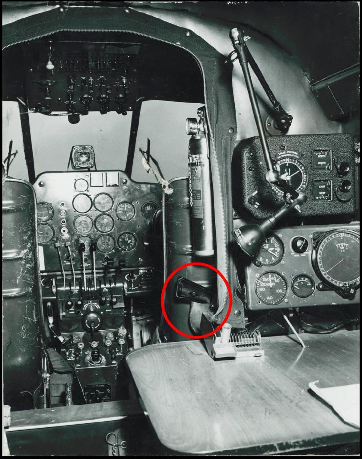
Usually the aircraft – when she was flying for the RCAF – would be able to stay in reliable radio communication. However, if they lost their method of communication – another way of doing it was by flares. Specifically taking an AN-M8 flare pistol – shown in the picture below attached to the back of the Co-Pilot’s seat – and screwing into the Flare Mount (by using the barrel locking lugs) that is above the Co Pilot’s Window. My concern here is that a blanking plate was installed over the Flare Mount hole – and what kind of shape was the Flare Mount after all this time? So, I did was I removed it, took a look at where the Flare Mount will be going – replaced the hardware (seeing that it’s quite old and I’m trying to eliminate as many little problems as possible) and mounted it again. (Like I said – just a quick tasking – but I just wanted to make sure.)
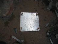
Photos L–R: Location of Flare Mount, Blanking Plate, and Historical Photo
Remove Control Column
Remove Duct Assembly (LH and RH)
Remove Engine and other Control Cables
Remove Control Cables and Pulleys from Main Cabin
Remove Old Cockpit Floor
Drill out Damaged Panel aft of Bulkhead 10
Can we get everything done that we want to – more importantly, did we get everything done that we wanted to? Unfortunately, we didn’t – and these are the PO’s that we either ran out time to do mainly due to all of the problems that we kept coming up against, or we wanted to do them but the weather wasn’t cooperating. (For example, drilling out the Damaged Panel aft of Bulkhead 10.)
Usually we are able to get all the tasking completed for the MRP, so - yes, it was disappointing to not get all the PO’s done that we wanted to. Keeping in mind, though, was the main goal of the MRP – Recce. We wanted to see how long it was going to take us to do something, and thus we could plan for it better. (After all, this is just the removal phase of the Periodic.) The Installation Phase – after all of the parts have been overhauled – is going to take just as long and be just as involved. (With the extra added benefit of handling a serviceable part that is very hard to replace – so don’t drop it!) So – no pressure!
Concurrent Activities
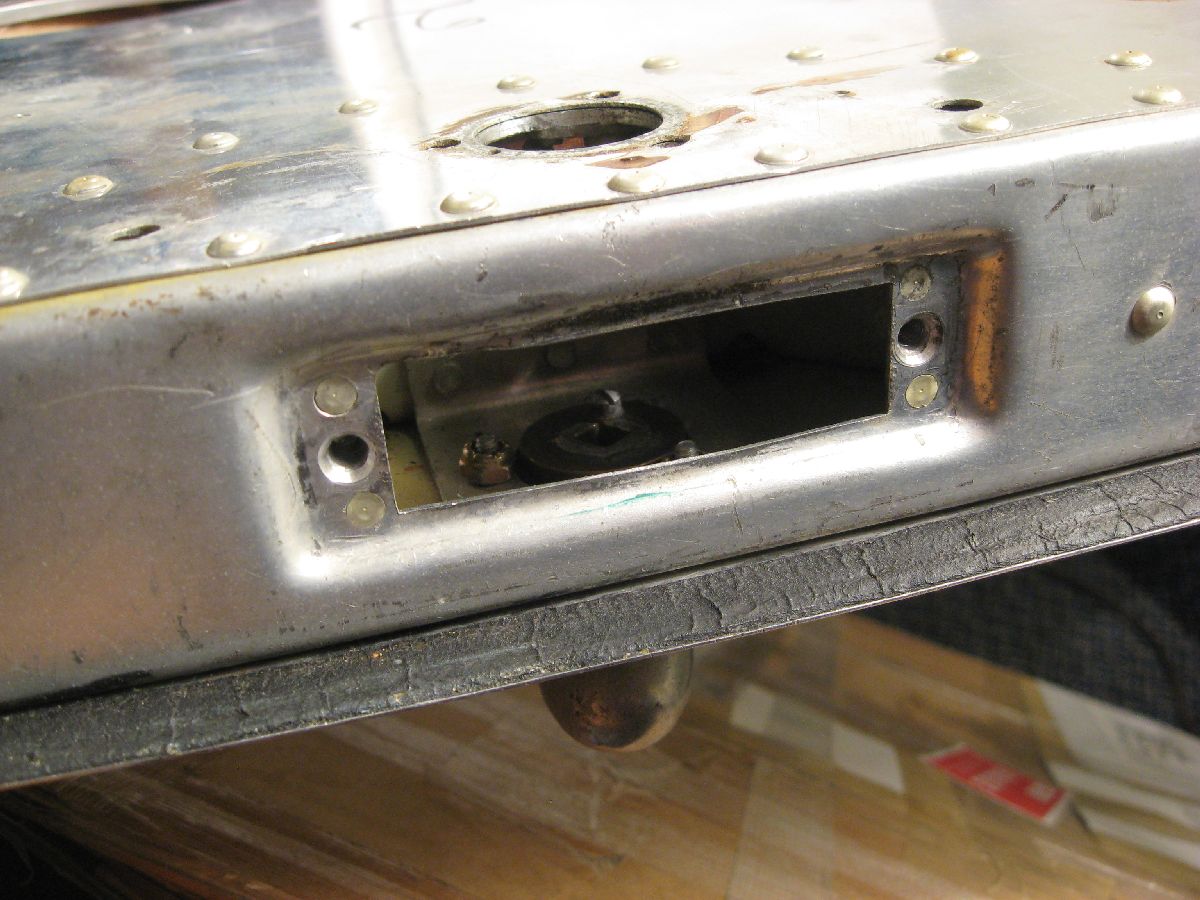
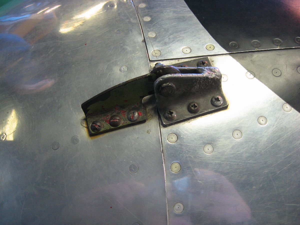
In addition to the work that we did on the MRP, we made the time to stop off at the Western Canadian Aviation Museum, located in Winnipeg. (And, upstairs they have a cockpit from an RCAF Expeditor – specifically CA-280.)
Neat idea, when you stop and think about it – making a cockpit available to be looked at up close. (Matter of fact, the museum made it so that this is a cockpit for kids to play in – which is really cool!) So, we made a point of taking a very close look at (complete with pictures) of another Expeditor cockpit.
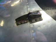
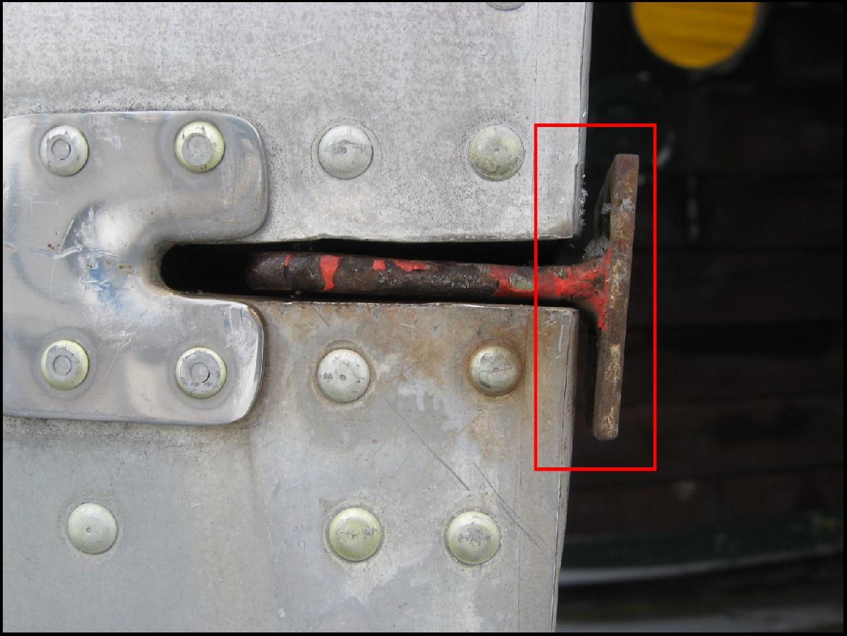
Close up of Nose Door Latch
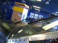
Close up of Port Windshield Wiper
Starboard Generator CB
Here’s the interesting thing about this photo: what we’re looking at is a way of dating the cockpit. Specifically, because the modification paperwork that was mentioned (and shown) earlier shows that this particular modification was done on 15 OCT 68 – which means that this cockpit can be dated to prior to 15 Oct 68. (In addition to that, it’s an interesting bit of comparison between what we removed on the MRP and what the museum is displaying.)
Centre Console
For sure, maintaining more than a working knowledge of the RCAF Maintenance Manuals isn’t easy. But, it’s a skill that’s needed when you’ve specialized in RCAF D Model Expeditors – and it’s something that you always rely on. If you take a look at the photos of the repair scheme paperwork – issued 16 NOV 64 – it has to do with making that kind of modification to the Centre Console. (And, if you take a look at the earlier photos of the Centre Console mounted in Expeditor 2339, you’ll see that this repair scheme wasn’t installed.)
X-Country travel completed, every one got home safe, all the tools are unpacked - and they were cleaned and oiled. Does that mean that this MRP is completed? To be honest – no. There are still the photos to go over, paperwork to write up, analysis of the amount of time it took to complete the work plus other factors – and most important of all – the overhauling of parts. (On top of that, the next MRP is already being planned for – so it’s fair to say that this process never really ends.)
Many thanks for your patience in waiting for the posting of the updates (and the pictures) and I look forward to your comments, observations and questions.